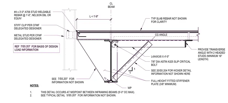
A gravity connection at a concrete slab edge is supported by a structural steel beam and cold-formed metal framing. A transverse angle with two headed studs is embedded at the slab edge, while metal studs and stiff clips are provided per the cold-formed metal framing delegated design. A full-height fitted stiffener plate with a minimum thickness of three-eighths of an inch is welded to the beam web. A kicker angle measuring L4x4x3/8 by four feet connects to the beam web using a seven-eighths-inch diameter ASTM A325 slip-critical bolt. Number four by three-foot A706 stud-weldable rebar is spaced at one foot six inches on center with Nelson D6L or equivalent anchors. This condition occurs at the midpoint between inframing beams at a maximum spacing of five feet on center.
NOTES: 1. THIS DETAIL OCCURS AT MIDPOINT BETWEEN INFRAMING BEAMS (5'-0" OC MAX). 2. SEE TYPICAL DETAIL FOR INFORMATION NOT SHOWN. TYP SLAB REBAR NOT SHOWN FOR CLARITY CL BEAM L < 1'-9" METAL STUD PER CFMF DELEGATED DESIGNER STIFF CLIP PER CFMF DELEGATED DESIGNER 5/S5.207 #4 x 3'-0" A706 STUD WELDABLE REBAR @ 1'-6", NELSON D6L OR EQUIV FULL-HEIGHT FITTED STIFFENER PLATE (3/8" MINIMUM) SEE FOR INFORMATION NOT SHOWN 7/S5.207 L4X4X3/8 X 4'-0" PROVIDE TRANSVERSE ANGLE WITH 2 HEADED STUDS (MINIMUM 16" LENGTH) 1 1 SEE 20/S5.204 FOR KICKER DETAIL INFORMATION NOT SHOWN HERE 7/8" DIA ASTM A325 SLIP CRITICAL BOLT WP 1" CG ANGLE REF FOR BASIS OF DESIGN LOAD INFORMATION 7/S5.207 NOTES: 1. THIS DETAIL OCCURS AT MIDPOINT BETWEEN INFRAMING BEAMS (5'-0" OC MAX). 2. SEE TYPICAL DETAIL FOR INFORMATION NOT SHOWN. TYP SLAB REBAR NOT SHOWN FOR CLARITY CL BEAM L < 1'-9" METAL STUD PER CFMF DELEGATED DESIGNER STIFF CLIP PER CFMF DELEGATED DESIGNER 5/S5.207 #4 x 3'-0" A706 STUD WELDABLE REBAR @ 1'-6", NELSON D6L OR EQUIV FULL-HEIGHT FITTED STIFFENER PLATE (3/8" MINIMUM) SEE FOR INFORMATION NOT SHOWN 7/S5.207 L4X4X3/8 X 4'-0" PROVIDE TRANSVERSE ANGLE WITH 2 HEADED STUDS (MINIMUM 16" LENGTH) 1 1 SEE 20/S5.204 FOR KICKER DETAIL INFORMATION NOT SHOWN HERE 7/8" DIA ASTM A325 SLIP CRITICAL BOLT WP 1" CG ANGLE REF FOR BASIS OF DESIGN LOAD INFORMATION 7/S5.207
Members view this detail in full resolution, download the CAD files (SVG, PDF), and can adapt it in the built-in CAD editor — export DXF, DWG, or PDF.
Start membership