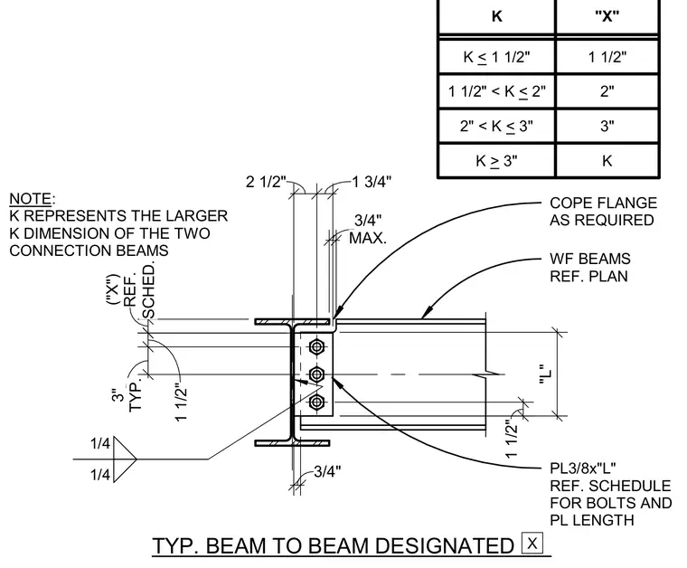
A wide-flange beam frames into another supporting wide-flange beam member. The supported beam features a coped top flange as required with a maximum three-quarter-inch clearance from the supporting member web. A three-eighths-inch thick plate of length "L" connects the members using bolts sized per the structural schedule. Fillet welds of one-quarter-inch size secure the connection assembly. A companion design table relates the "K" dimension of the larger connecting beam to the dimension "X" for plate positioning.
TYP. BEAM TO BEAM DESIGNATED NOTE: K REPRESENTS THE LARGER K DIMENSION OF THE TWO CONNECTION BEAMS COPE FLANGE AS REQUIRED WF BEAMS REF. PLAN PL3/8x"L" REF. SCHEDULE FOR BOLTS AND PL LENGTH X SCHED. ("X") REF. MAX. 3/4" 1/4 1/4 "L" 2 1/2" 1 3/4" 1 1/2" 1 1/2" TYP. 3" 3/4" K < 1 1/2" 1 1/2" K "X" 1 1/2" < K < 2" 2" 2" < K < 3" 3" K > 3" K
Members view this detail in full resolution, download the CAD files (SVG, PDF), and can adapt it in the built-in CAD editor — export DXF, DWG, or PDF.
Start membership