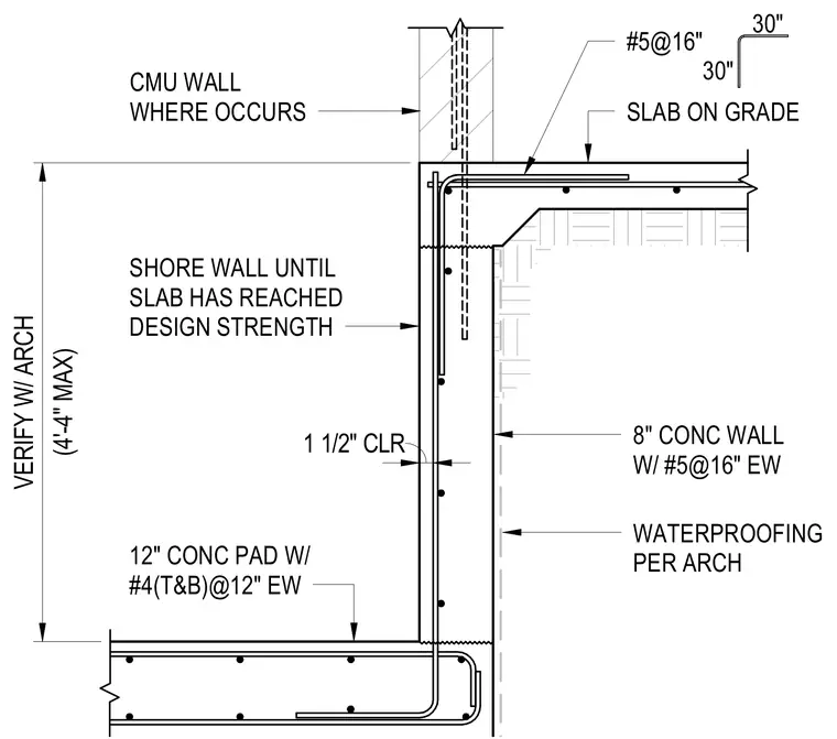
A concrete foundation and wall assembly for an elevator pit consists of a twelve-inch concrete pad reinforced with number four bars top and bottom at twelve inches each way. The eight-inch concrete wall features number five reinforcing bars at sixteen inches each way and exterior waterproofing per architectural drawings with one and one-half inch clearance. A slab on grade abuts the top of the wall, which includes a CMU wall where required up to a maximum height of four feet four inches verified with architectural plans. Shore the wall until the slab has reached design strength.
12" CONC PAD W/ #4(T&B)@12" EW WATERPROOFING PER ARCH 8" CONC WALL W/ #5@16" EW SHORE WALL UNTIL SLAB HAS REACHED DESIGN STRENGTH SLAB ON GRADE 30" 30" #5@16" CMU WALL WHERE OCCURS (4'-4" MAX) VERIFY W/ ARCH 1 1/2" CLR
Members view this detail in full resolution, download the CAD files (SVG, PDF), and can adapt it in the built-in CAD editor — export DXF, DWG, or PDF.
Start membership