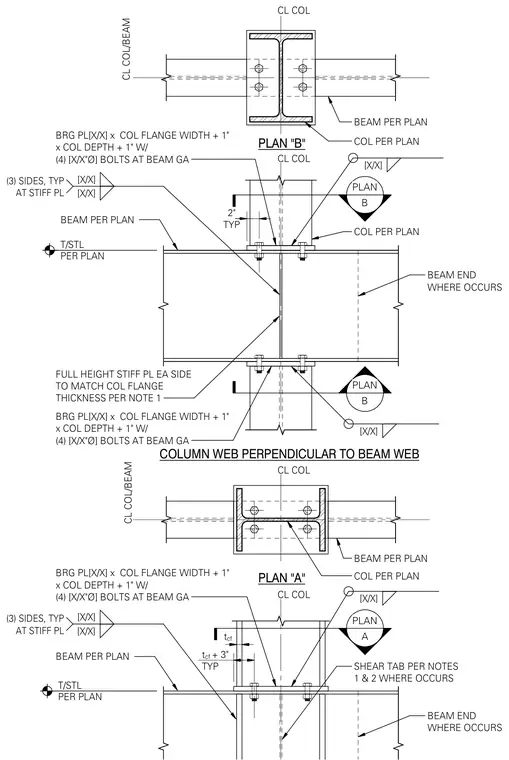
A structural steel connection features the column web oriented perpendicular to the beam web. The assembly features a bearing plate sized to the column flange width plus one inch by the column depth plus one inch, secured with four anchor bolts at the beam gauge. Full-height stiffener plates are provided on each side of the column matching the column flange thickness, welded on three sides typically at the stiffener plates. A shear tab connects the beam per plans as indicated, accompanied by plan views A and B detailing the layout.
PLAN A PLAN B PLAN B CL COL BEAM PER PLAN T/STL PER PLAN [X/X] [X/X] (3) SIDES, TYP AT STIFF PL COLUMN WEB PERPENDICULAR TO BEAM WEB CL COL BEAM PER PLAN T/STL PER PLAN FULL HEIGHT STIFF PL EA SIDE TO MATCH COL FLANGE THICKNESS PER NOTE 1 BEAM END WHERE OCCURS [X/X] [X/X] (3) SIDES, TYP AT STIFF PL BEAM END WHERE OCCURS SHEAR TAB PER NOTES 1 & 2 WHERE OCCURS PLAN "A" BEAM PER PLAN COL PER PLAN CL COL CL COL/BEAM BRG PL[X/X] x COL FLANGE WIDTH + 1" x COL DEPTH + 1" W/ (4) [X/X"Ø] BOLTS AT BEAM GA [X/X] COL PER PLAN [X/X] BRG PL[X/X] x COL FLANGE WIDTH + 1" x COL DEPTH + 1" W/ (4) [X/X"Ø] BOLTS AT BEAM GA BRG PL[X/X] x COL FLANGE WIDTH + 1" x COL DEPTH + 1" W/ (4) [X/X"Ø] BOLTS AT BEAM GA [X/X] TYP 2" CL COL/BEAM PLAN "B" CL COL BEAM PER PLAN COL PER PLAN t cf t cf + 3" TYP 0 0 0 0 \ $ 0 <> TT L 4 " / urn F r / $ 0 0
Members view this detail in full resolution, download the CAD files (SVG, PDF), and can adapt it in the built-in CAD editor — export DXF, DWG, or PDF.
Start membership