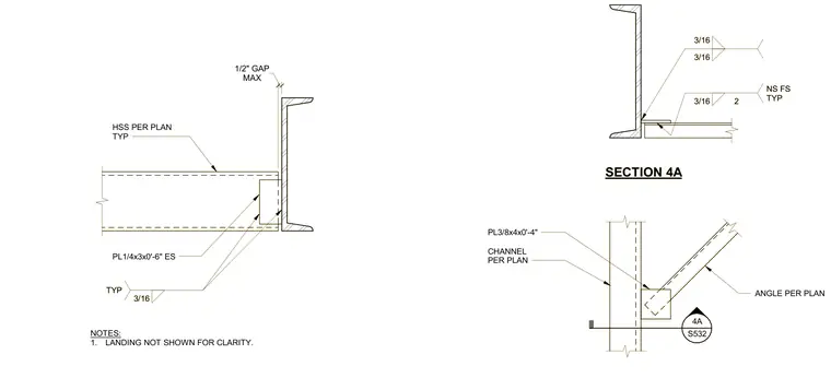
A hollow structural section beam frames into a channel member sized per plan with a maximum one-half inch gap. A three-eighths by four inch by zero-foot-four-inch plate and an angle sized per plan connect the members with typical three-sixteenths inch fillet welds on both near and far sides. A one-quarter by three by zero-foot-six-inch plate is welded each side with three-sixteenths inch fillet welds. The stair landing is omitted for clarity.
SECTION 4A S532 4A CHANNEL PER PLAN ANGLE PER PLAN PL3/8x4x0'-4" 3/16 3/16 3/16 2 NS FS TYP HSS PER PLAN TYP PL1/4x3x0'-6" ES 3/16 TYP NOTES: 1. LANDING NOT SHOWN FOR CLARITY. MAX 1/2" GAP SECTION 4A S532 4A CHANNEL PER PLAN ANGLE PER PLAN PL3/8x4x0'-4" 3/16 3/16 3/16 2 NS FS TYP HSS PER PLAN TYP PL1/4x3x0'-6" ES 3/16 TYP NOTES: 1. LANDING NOT SHOWN FOR CLARITY. MAX 1/2" GAP
Members view this detail in full resolution, download the CAD files (SVG, PDF), and can adapt it in the built-in CAD editor — export DXF, DWG, or PDF.
Start membership