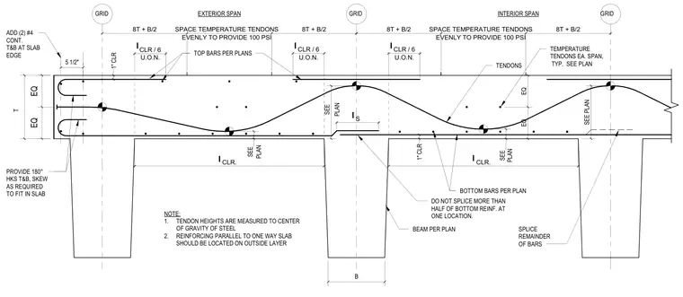
A one-way post-tensioned concrete slab is supported by cast-in-place concrete beams. The section details the profiles of draped post-tensioning tendons spanning across exterior and interior bays, with tendon heights measured to the center of gravity of the steel. Top and bottom reinforcing bars are placed per plan with specified clearances, including additional continuous number four bars with 180-degree hooks at the slab edge. Bottom reinforcement splices are staggered to prevent splicing more than half of the bars at one location. Temperature tendons are spaced evenly across each span to provide the required compression.
GRID INTERIOR SPAN TOP BARS PER PLANS 1" CLR l EQ EQ BOTTOM BARS PER PLAN BEAM PER PLAN 1" CLR TEMPERATURE TENDONS EA. SPAN, TYP. SEE PLAN EXTERIOR SPAN TENDONS PLAN SEE SEE PLAN NOTE: 1. TENDON HEIGHTS ARE MEASURED TO CENTER OF GRAVITY OF STEEL 2. REINFORCING PARALLEL TO ONE WAY SLAB SHOULD BE LOCATED ON OUTSIDE LAYER GRID GRID EQ EQ PLAN SEE PLAN SEE ADD (2) #4 CONT. T&B AT SLAB EDGE S U.O.N. CLR / 6 CLR. l CLR. l 5 1/2" B DO NOT SPLICE MORE THAN HALF OF BOTTOM REINF. AT ONE LOCATION. SPLICE REMAINDER OF BARS T 8T + B/2 EVENLY TO PROVIDE 100 PSI SPACE TEMPERATURE TENDONS 8T + B/2 8T + B/2 EVENLY TO PROVIDE 100 PSI SPACE TEMPERATURE TENDONS 8T + B/2 U.O.N. CLR / 6 U.O.N. CLR / 6 l l l PROVIDE 180° HKS T&B, SKEW AS REQUIRED TO FIT IN SLAB
Members view this detail in full resolution, download the CAD files (SVG, PDF), and can adapt it in the built-in CAD editor — export DXF, DWG, or PDF.
Start membership