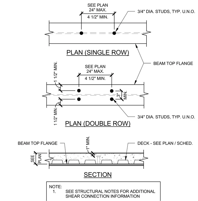
Layout requirements for three-quarter inch diameter shear studs welded to the beam top flange in both single and double configurations. The single row layout requires a minimum edge distance of four and one-half inches with a maximum spacing of twenty-four inches as sized per plan unless noted otherwise. The double row configuration provides a three-inch minimum transverse spacing between studs with one and one-half inch minimum edge clearances. The section view details the metal deck and concrete placement over the steel beam, maintaining a one-inch minimum concrete cover over the top of the shear stud. Additional shear connection information is referenced to the general structural notes.
PLAN (SINGLE ROW) PLAN (DOUBLE ROW) SECTION NOTE: 1. SEE STRUCTURAL NOTES FOR ADDITIONAL SHEAR CONNECTION INFORMATION BEAM TOP FLANGE 3/4" DIA. STUDS, TYP. U.N.O. DECK - SEE PLAN / SCHED. BEAM TOP FLANGE 1" MIN. 4 1/2" MIN. SEE PLAN 24" MAX. 4 1/2" MIN. SEE PLAN 24" MAX. 1 1/2" MIN. 3/4" DIA. STUDS, TYP. U.N.O. MIN. 3" PLAN SEE 1 1/2" MIN.
Members view this detail in full resolution, download the CAD files (SVG, PDF), and can adapt it in the built-in CAD editor — export DXF, DWG, or PDF.
Start membership