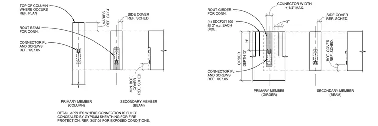
Concealed heavy timber framing details show a proprietary concealed connector plate inserted into routed slots in the wood members and fastened with four SDCF271100 screws spaced at two inches on center on each side. The primary timber column or girder is routed to accept the connector plate with a maximum width clearance of one-quarter inch, maintaining specified side and bottom cover dimensions referenced in the schedule. The secondary timber beam aligns with the connection and is routed to receive the mating half of the connector plate and screws. This detail applies where the structural connection is fully concealed by gypsum sheathing for fire protection, with exposed conditions referenced elsewhere.
ROUT GIRDER FOR CONN. CONNECTOR PL AND SCREWS REF. 1/S7.05 PRIMARY MEMBER (GIRDER) REF. SCHED. BOT. COVER SECONDARY MEMBER (BEAM) + 1/4" MAX. CONNECTOR WIDTH REF. SCHED. SIDE COVER DEPTH 'D' GIRDER 'H' (4) SDCF271100 @ 2" o.c. EACH SIDE 2" 2" PRIMARY MEMBER (COLUMN) SECONDARY MEMBER (BEAM) TOP OF COLUMN WHERE OCCURS REF. PLAN ROUT BEAM FOR CONN. CONNECTOR PL AND SCREWS REF. 1/S7.05 REF. S7.04 VARIES REF. SCHED. SIDE COVER REF. SCHED MIN. BOT. COVER DETAIL APPLIES WHERE CONNECTION IS FULLY CONCEALED BY GYPSUM SHEATHING FOR FIRE PROTECTION. REF. 3/S7.05 FOR EXPOSED CONDITIONS.
Members view this detail in full resolution, download the CAD files (SVG, PDF), and can adapt it in the built-in CAD editor — export DXF, DWG, or PDF.
Start membership