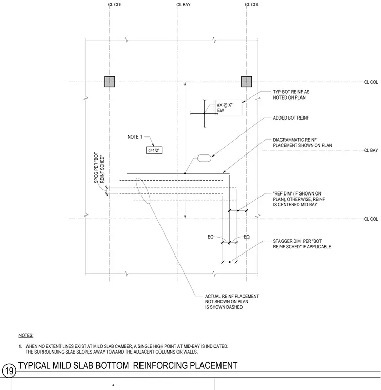
Typical mild slab bottom reinforcing placement details show the layout of reinforcing bars relative to column and bay centerlines. Bottom reinforcing is spaced per the bottom reinforcing schedule with staggered dimensions applied where applicable. Diagrammatic reinforcing placement is indicated on the plan with actual placement shown dashed. A single high point at mid-bay is indicated for mild slab camber when no extent lines exist, with the surrounding slab sloping toward adjacent columns or walls. Reference dimensions center the reinforcing mid-bay when not otherwise specified on the plan.
STAGGER DIM PER "BOT REINF SCHED" IF APPLICABLE DIAGRAMMATIC REINF PLACEMENT SHOWN ON PLAN NOTE 1 NOTES: 1. WHEN NO EXTENT LINES EXIST AT MILD SLAB CAMBER, A SINGLE HIGH POINT AT MID-BAY IS INDICATED. THE SURROUNDING SLAB SLOPES AWAY TOWARD THE ADJACENT COLUMNS OR WALLS. ADDED BOT REINF TYP BOT REINF AS NOTED ON PLAN #X @ X" EW ACTUAL REINF PLACEMENT NOT SHOWN ON PLAN IS SHOWN DASHED CL BAY CL COL CL COL CL BAY CL COL "REF DIM" (IF SHOWN ON PLAN), OTHERWISE, REINF IS CENTERED MID-BAY c=1/2" 24" EQ 12" EQ 30" CL COL SPCG PER "BOT REINF SCHED" 4 19 TYPICAL MILD SLAB BOTTOM REINFORCING PLACEMENT
Members view this detail in full resolution, download the CAD files (SVG, PDF), and can adapt it in the built-in CAD editor — export DXF, DWG, or PDF.
Start membership