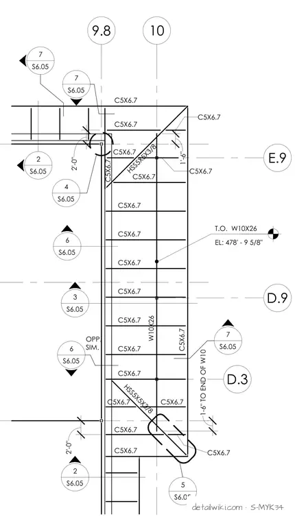
The plan details the layout of steel framing members including W-shape beams (W10X26), channel sections (C5X6.7), and hollow structural sections (HSS5X5X3/8) configured with diagonal bracing at corners. Grid lines (9.8, 10, E.9, D.9, D.3) and elevation callouts indicate the spatial alignment and top-of-steel elevations (T.O. W10X26 at EL: 478'-9 5/8"). Section and detail reference bubbles are provided throughout to indicate connections and interfaces with other construction details.
Text on the drawing
10 9.8 W10X26 HSS5X5X3/8 HSS5X5X3/8 C5X6.7 C5X6.7 2'-0" C5X6.7 C5X6.7 C5X6.7 C5X6.7 C5X6.7 1'-6" EL: 478' - 9 5/8" 2'-0" T.O. W10X26 C5X6.7 C5X6.7 C5X6.7 C5X6.7 C5X6.7 C5X6.7 C5X6.7 C5X6.7 C5X6.7 C5X6.7 C5X6.7 C5X6.7 7 S6.05 2 S6.05 6 S6.05 7 S6.05 4 S6.05 2 S6.05 7 S6.05 5 S6.05 3 S6.05 6 S6.05 OPP. SIM. E.9 D.9 D.3 1-6" TO END OF W10 C5X6.7
Members view this detail in full resolution, download the CAD files (SVG, PDF), and open any detail in the built-in CAD editor to edit and export DXF or DWG.
Sign in to subscribe