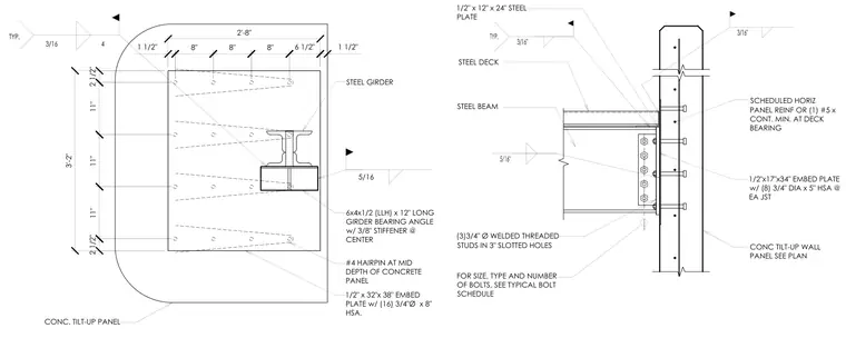
A steel girder frames into a concrete tilt-up wall panel using a 6x4x1/2-inch by 12-inch long girder bearing angle with a three-eighth-inch stiffener at the center, welded to a half-inch by 32-inch by 38-inch embed plate with sixteen three-quarter-inch diameter by 8-inch headed stud anchors. A steel beam connects to a half-inch by 17-inch by 34-inch embed plate with eight three-quarter-inch diameter by 5-inch headed stud anchors in the concrete tilt-up wall panel. Number four hairpins are placed at the mid-depth of the concrete panel around the embed plate. A half-inch by 12-inch by 24-inch steel plate features threaded studs in three-inch slotted holes at the steel deck bearing location.
11" 11" 11" 2 1/2" 3'-2" 2 1/2" 6 1/2" 1 1/2" 2'-8" 8" 8" 8" 1 1/2" STEEL GIRDER 6x4x1/2 (LLH) x 12" LONG GIRDER BEARING ANGLE w/ 3/8" STIFFENER @ CENTER 1/2" x 32"x 38" EMBED 3/$7(Z[ HSA. #4 HAIRPIN AT MID DEPTH OF CONCRETE PANEL CONC. TILT-UP PANEL 5/16 STEEL BEAM STEEL DECK CONC TILT-UP WALL PANEL SEE PLAN 1/2"x17"x34" EMBED PLATE w/ (8) 3/4" DIA x 5" HSA @ EA JST SCHEDULED HORIZ PANEL REINF OR (1) #5 x CONT. MIN. AT DECK BEARING FOR SIZE, TYPE AND NUMBER OF BOLTS, SEE TYPICAL BOLT SCHEDULE 1/2" x 12" x 24" STEEL PLATE :(/'('7+5($'(' STUDS IN 3" SLOTTED HOLES
Members view this detail in full resolution, download the CAD files (SVG, PDF), and can adapt it in the built-in CAD editor — export DXF, DWG, or PDF.
Start membership