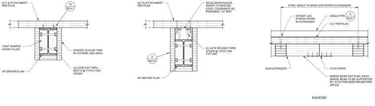
A glulam barge beam splice rests on a wide-flange steel beam and cross-laminated timber deck assembly. The wide-flange beam receives continuous shaped wood filler secured with two three-quarter-inch diameter A307 through-bolts at four-foot centers with countersunk heads, alongside welded threaded studs at twelve-inch centers. A solid sawn nailer accommodates steel tolerances up to one-half inch, supporting a steel angle that spans continuously between outriggers. Glulam outriggers connect using three-quarter-inch by eight-inch lag screws centered in the outrigger, reinforced by CS16 straps. Each barge beam requires a minimum of three supporting outriggers before the splice location, with shaped glulam trim provided by others per architectural drawings.
CLT & ATTACHMENT PER PLAN WF BM PER PLAN (2) 3/4"Ø A307 THRU BOLTS @ 4'-0"CC CSK HEADS CONT SHAPED WOOD FILLER SHAPED GLULAM TRIM BY OTHERS, SEE ARCH 14 S5.4.1 CLT & ATTACHMENT PER PLAN WF BM PER PLAN (2) 3/4"Ø WELDED THRD STUDS @ 12"CC CSK TYP UNO 5 S5.5.2 SOLID SAWN NAILER, SHAPE TO PROVIDE STEEL TOLERANCE AS REQUIRED, 1/2" MAX STEEL ANGLE TO SPAN CONT BTWN OUTRIGGERS ANGLE PER 8 S5.4.1 CLT PER PLAN 3/4"Øx8" LAG SCREW CNTRD IN OUTRIGGER GLB OUTRIGGER CS16 STRAP BARGE BEAM PER PLAN. EACH BARGE BEAM TO BE SUPPORTED BY (3) OUTRIGGERS MIN BEFORE SPLICE ELEVATION
Members view this detail in full resolution, download the CAD files (SVG, PDF), and can adapt it in the built-in CAD editor — export DXF, DWG, or PDF.
Start membership