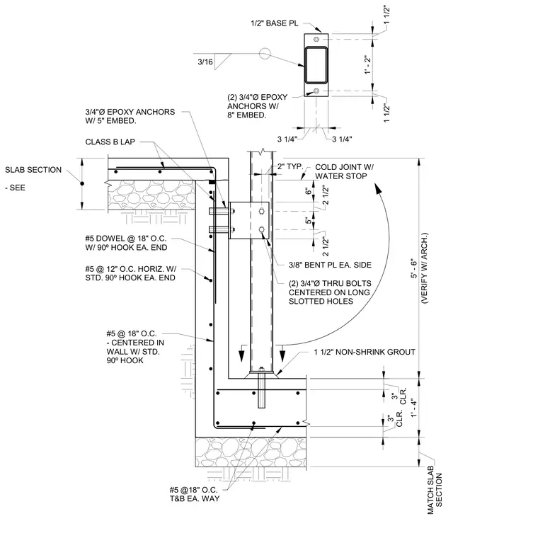
An elevator pit wall transitions to a concrete slab via a cold joint with water stop, integrating steel guide rail support brackets anchored to the concrete. The reinforced concrete pit wall incorporates number five horizontal dowels at twelve inches on center with standard ninety-degree hooks at each end, plus number five reinforcing bars at eighteen inches on center top and bottom each way. Two three-quarter-inch diameter epoxy anchors with eight-inch embedment secure the guide rail base plate, while three-eighths-inch bent plates on each side use two three-quarter-inch diameter through-bolts centered on long slotted holes. A one-and-a-half-inch layer of non-shrink grout sits beneath the base plate, and three-quarter-inch epoxy anchors with five-inch embedment tie the side bracket assembly into the elevator pit wall. Additional slab connection details include a class B lap splice and number five dowels at eighteen inches on center with ninety-degree hooks.
SECTION MATCH SLAB 1' - 4" (VERIFY W/ ARCH.) 5' - 6" CLR. 3" CLR. 3" 1/2" BASE PL 3/16 (2) 3/4"Ø EPOXY ANCHORS W/ 8" EMBED. CLASS B LAP COLD JOINT W/ WATER STOP #5 DOWEL @ 18" O.C. W/ 90º HOOK EA. END #5 @ 12" O.C. HORIZ. W/ STD. 90º HOOK EA. END #5 @ 18" O.C. - CENTERED IN WALL W/ STD. 90º HOOK #5 @18" O.C T&B EA. WAY 1 1/2" NON-SHRINK GROUT . 1 1/2" 1' - 2" 1 1/2" 3 1/4" 3 1/4" SLAB SECTION - SEE (2) 3/4"Ø THRU BOLTS CENTERED ON LONG SLOTTED HOLES 6" 2 1/2" 5" 2 1/2" 3/4"Ø EPOXY ANCHORS W/ 5" EMBED. 2" TYP. 3/8" BENT PL EA. SIDE
Members view this detail in full resolution, download the CAD files (SVG, PDF), and can adapt it in the built-in CAD editor — export DXF, DWG, or PDF.
Start membership