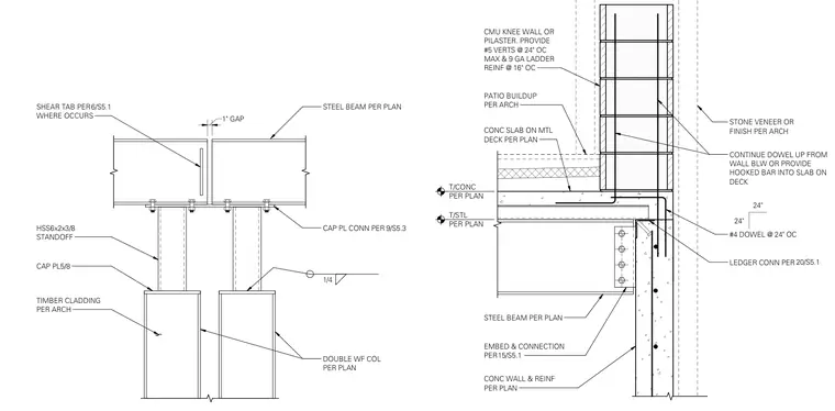
A concrete masonry unit knee wall or pilaster is supported by a concrete slab on metal deck over a structural steel beam and double wide-flange column assembly. The CMU wall incorporates number 5 vertical reinforcing bars spaced at twenty-four inches on center maximum with nine-gauge ladder reinforcing at sixteen inches on center, along with stone veneer or architectural finish and dowel continuity from the wall below or hooked bars into the slab on deck. A patio buildup sits on the concrete slab, which is tied to the supporting steel beam via ledger connections and embed plates per plan. Below the slab, double wide-flange columns feature a five-eighth-inch thick cap plate welded with a quarter-inch fillet weld, supporting an HSS6x2x3/8 standoff with a one-inch gap and a shear tab connection where indicated.
TIMBER CLADDING PER ARCH DOUBLE WF COL PER PLAN CAP PL5/8 1/4 HSS6x2x3/8 STANDOFF 1" GAP SHEAR TAB PER WHERE OCCURS 6/S5.1 STEEL BEAM PER PLAN CAP PL CONN PER 9/S5.3 T/STL PER PLAN CONTINUE DOWEL UP FROM WALL BLW OR PROVIDE HOOKED BAR INTO SLAB ON DECK PATIO BUILDUP PER ARCH CONC SLAB ON MTL DECK PER PLAN STONE VENEER OR FINISH PER ARCH CMU KNEE WALL OR PILASTER. PROVIDE #5 VERTS @ 24" OC MAX & 9 GA LADDER REINF @ 16" OC CONC WALL & REINF PER PLAN LEDGER CONN PER STEEL BEAM PER PLAN EMBED & CONNECTION PER 20/S5.1 15/S5.1 #4 DOWEL @ 24" OC 24" 24" T/CONC PER PLAN
Members view this detail in full resolution, download the CAD files (SVG, PDF), and can adapt it in the built-in CAD editor — export DXF, DWG, or PDF.
Start membership