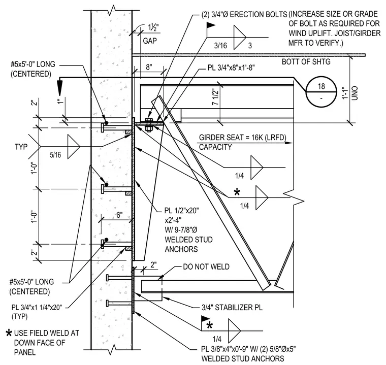
This assembly features a steel truss girder supported by a 1/2-inch by 20-inch by 2-foot-4-inch embedded steel plate cast into a concrete wall, secured with nine 7/8-inch diameter welded stud anchors. The girder seat is designed for a 16-kip Load and Resistance Factor Design capacity and includes a 3/4-inch by 8-inch by 1-foot-8-inch plate connected to the girder with two 3/4-inch diameter erection bolts. The connection is reinforced with a 3/4-inch stabilizer plate and a 3/8-inch by 9-inch plate with two 5/8-inch diameter welded stud anchors at the lower connection point. Fillet welds of 1/4-inch and 5/16-inch are specified throughout, with a note to field weld at the down face of the panel and to leave the lower stabilizer plate unwelded to the girder. The joist or girder manufacturer is responsible for verifying bolt sizes and grades to accommodate wind uplift requirements.
1" 2" 2" 1'-0" 1'-0" 2" DO NOT WELD PL 3/4"x8"x1'-8" (2) 3/4"Ø ERECTION BOLTS 1'-1" UNO PL 1/2"x20" x2'-4" W/ 9-7/8"Ø WELDED STUD ANCHORS 1 12 " 6" GAP GIRDER SEAT = 16K (LRFD) CAPACITY BOTT OF SHTG #5x5'-0" LONG (CENTERED) #5x5'-0" LONG (CENTERED) 18 - * 1/4 1/4 3/16 3 5/16 TYP 8" 7 1/2" (INCREASE SIZE OR GRADE OF BOLT AS REQUIRED FOR WIND UPLIFT. JOIST/GIRDER MFR TO VERIFY.)
Members view this detail in full resolution, download the CAD files (SVG, PDF), and can adapt it in the built-in CAD editor — export DXF, DWG, or PDF.
Start membership