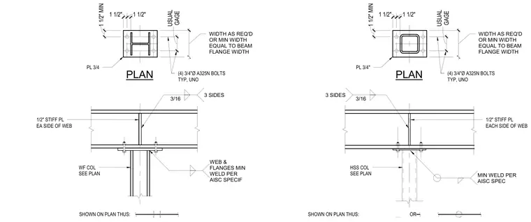
A continuous wide-flange beam is supported by either a wide-flange column or a hollow structural section column sized per plan. A three-quarter-inch plate is welded to the top of the column and connected to the beam flange with four three-quarter-inch-diameter A325N bolts typically unless noted otherwise. One-half-inch stiffener plates are welded to each side of the beam web aligned with the column flanges using three-sixteenth-inch fillet welds on three sides. Additional welding at the web and flanges conforms to minimum AISC specifications. Edge distances and gauges maintain standard minimum dimensions of one and one-half inches.
1/2" STIFF PL EA SIDE OF WEB WF COL SEE PLAN PLAN PL 3/4 (4) 3/4"Ø A325N BOLTS TYP, UNO WIDTH AS REQ'D OR MIN WIDTH EQUAL TO BEAM FLANGE WIDTH 3/16 3 SIDES WEB & FLANGES MIN WELD PER AISC SPECIF GAGE USUAL . 1 1/2" MIN 1 1/2" 1 1/2" SHOWN ON PLAN THUS: SHOWN ON PLAN THUS: OR HSS COL SEE PLAN 1/2" STIFF PL EACH SIDE OF WEB 3/16 3 SIDES MIN WELD PER AISC SPEC PLAN PL 3/4" (4) 3/4"Ø A325N BOLTS TYP, UNO WIDTH AS REQ'D OR MIN WIDTH EQUAL TO BEAM FLANGE WIDTH GAGE USUAL . 1 1/2" MIN 1 1/2" 1 1/2"
Members view this detail in full resolution, download the CAD files (SVG, PDF), and can adapt it in the built-in CAD editor — export DXF, DWG, or PDF.
Start membership