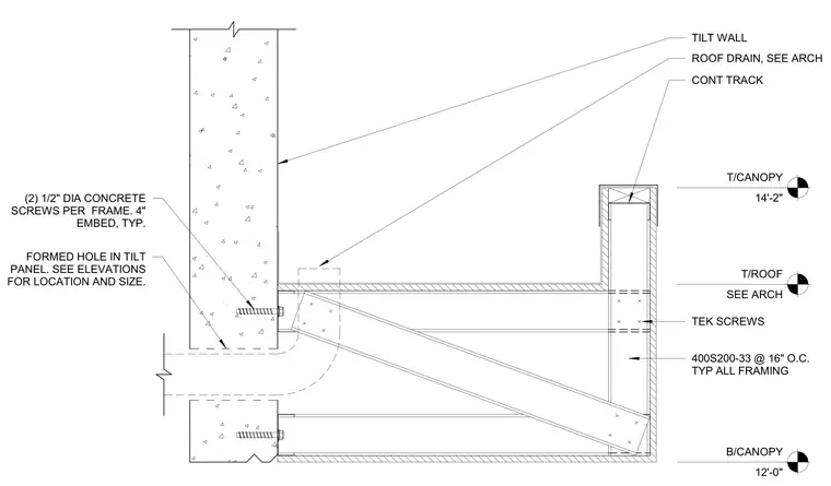
The canopy frame consists of 400S200-33 cold-formed steel members spaced at 16 inches on center, with all framing connections secured using Tek screws. The assembly is anchored to the concrete tilt-up wall panel using two 1/2-inch diameter concrete screws per frame, providing a 4-inch embedment depth. A formed hole is provided in the tilt-up panel to accommodate the roof drain, with specific locations and sizes referenced in the architectural elevations. The canopy top elevation is set at 14'-2", while the bottom elevation is at 12'-0".
B/CANOPY 12'-0" T/ROOF SEE ARCH T/CANOPY 14'-2" TILT WALL ROOF DRAIN, SEE ARCH FORMED HOLE IN TILT PANEL. SEE ELEVATIONS FOR LOCATION AND SIZE. CONT TRACK 400S200-33 @ 16" O.C. TYP ALL FRAMING TEK SCREWS (2) 1/2" DIA CONCRETE SCREWS PER FRAME. 4" EMBED, TYP.
Members view this detail in full resolution, download the CAD files (SVG, PDF), and can adapt it in the built-in CAD editor — export DXF, DWG, or PDF.
Start membership