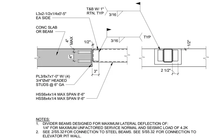
An elevator divider beam connects to a concrete slab or beam via a three-eighths-inch by seven-inch by one-foot-zero-inch embed plate welded with four three-quarter-inch diameter by six-inch headed studs at six-inch gauge. Angle clips measuring three by two-and-a-half by one-quarter inch by five inches long are welded to each side of the connection with three-sixteenths-inch fillet welds featuring one-inch returns top and bottom. The hollow structural section divider beam comprises either an HSS six by four by one-quarter with a maximum span of eight feet six inches or an HSS eight by four by one-quarter with a maximum span of nine feet six inches. Divider beams are designed for a maximum lateral deflection of one-quarter inch for a maximum unfactored service normal and seismic load of four point two kips.
3/16 T&B W/ 1" RTN, TYP 3/16 TYP L3x2-1/2x1/4x0'-5" EA SIDE PL3/8x7x1'-0" W/ (4) 3/4"Øx6" HEADED STUDS @ 6" GA HSS6x4x1/4 MAX SPAN 8'-6" HSS8x4x1/4 MAX SPAN 9'-6" NOTES: 1. DIVIDER BEAMS DESIGNED FOR MAXIMUM LATERAL DEFLECTION OF: 1/4" FOR MAXIMUM UNFACTORED SERVICE NORMAL AND SEISMIC LOAD OF 4.2K 2. SEE FOR CONNECTION TO STEEL BEAMS. SEE FOR CONNECTION TO ELEVATOR PIT WALL. 2 1/2" 1/2" 3" 4" 1/2" MAX 4" CONC SLAB OR BEAM 2/S5.32 5/S5.32
Members view this detail in full resolution, download the CAD files (SVG, PDF), and can adapt it in the built-in CAD editor — export DXF, DWG, or PDF.
Start membership