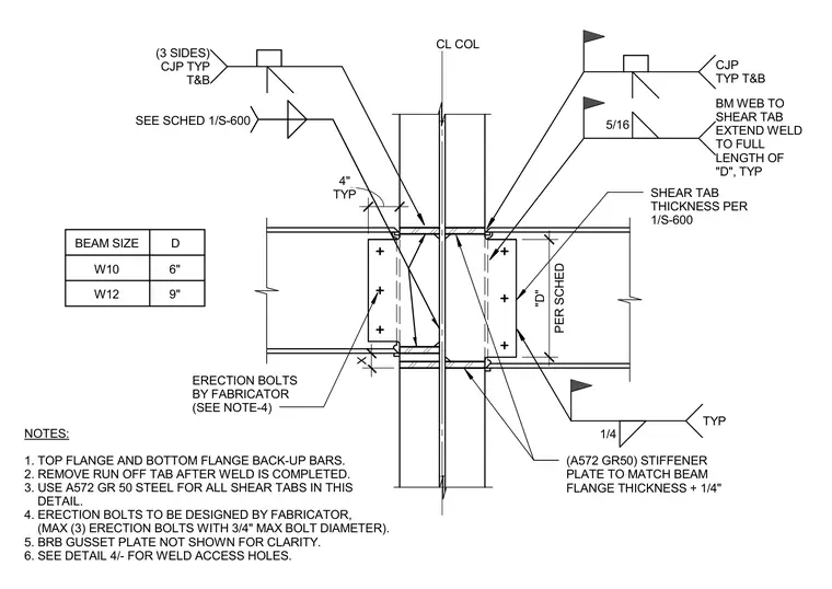
A structural steel beam-to-column moment connection incorporates a buckling-restrained brace gusset plate. The wide-flange beam connects to the column centerline using complete joint penetration groove welds on both the top and bottom flanges, backed by standard steel back-up bars that require run-off tabs to be removed after welding. A single-plate shear tab connects the beam web with a 5/16-inch fillet weld extending the full length of dimension 'D', which varies from 6 inches for W10 beams to 9 inches for W12 beams. Erection bolts are designed by the fabricator, limited to a maximum of three bolts with a 3/4-inch maximum diameter. Grade A572 Grade 50 steel is specified for all shear tabs and for stiffener plates, which match the beam flange thickness plus a 1/4-inch clearance.
(A572 GR50) STIFFENER PLATE TO MATCH BEAM FLANGE THICKNESS + 1/4" CL COL SEE SCHED 1/S-600 NOTES: 1. TOP FLANGE AND BOTTOM FLANGE BACK-UP BARS. 2. REMOVE RUN OFF TAB AFTER WELD IS COMPLETED. 3. USE A572 GR 50 STEEL FOR ALL SHEAR TABS IN THIS DETAIL. 4. ERECTION BOLTS TO BE DESIGNED BY FABRICATOR, (MAX (3) ERECTION BOLTS WITH 3/4" MAX BOLT DIAMETER). 5. BRB GUSSET PLATE NOT SHOWN FOR CLARITY. 6. SEE DETAIL 4/- FOR WELD ACCESS HOLES. SHEAR TAB THICKNESS PER 1/S-600 TYP 4" X ERECTION BOLTS BY FABRICATOR (SEE NOTE-4) PER SCHED "D" 5/16 BM WEB TO SHEAR TAB EXTEND WELD TO FULL LENGTH OF "D", TYP (3 SIDES) CJP TYP T&B CJP TYP T&B 1/4 TYP BEAM SIZE D W10 6" W12 9"
Members view this detail in full resolution, download the CAD files (SVG, PDF), and can adapt it in the built-in CAD editor — export DXF, DWG, or PDF.
Start membership