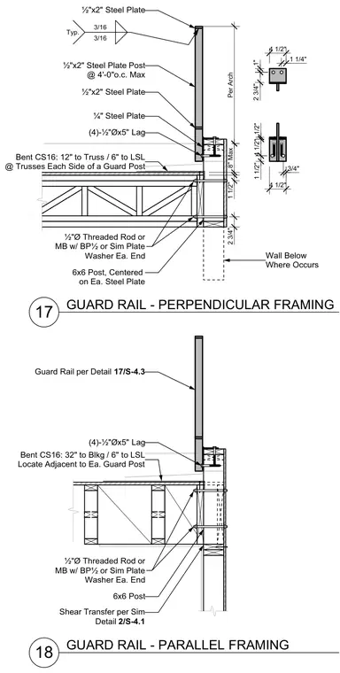
Guard rail post connections to framing for both perpendicular and parallel configurations comprise a one-half by two-inch steel plate post spaced at a maximum of four feet on center, welded with three-sixteenths inch fillet welds to base plates. Four one-half inch diameter by five-inch long lag screws secure the base connection to the framing below. Wood framing includes six-by-six posts centered on each steel plate, tied with one-half inch diameter threaded rods or machine bolts equipped with plate washers at each end. Bent CS16 straps are specified at trusses on each side of the guard post and adjacent to blocking as noted.
17 18 ½"x2" Steel Plate Post @ 4'-0"o.c. Max ½"x2" Steel Plate ½"x2" Steel Plate ¼" Steel Plate (4)-½"Øx5" Lag ½"Ø Threaded Rod or MB w/ BP½ or Sim Plate Washer Ea. End 6x6 Post, Centered on Ea. Steel Plate Bent CS16: 12" to Truss / 6" to LSL @ Trusses Each Side of a Guard Post 3/16 3/16 Typ. 4 1/2" 1 1/2" 4 1/2" 1/2" 3/4" 2 3/4" 1" 4 1/2" 1 1/4" Per Arch 8" Max 1 1/2" 2 3/4" Wall Below Where Occurs GUARD RAIL - PERPENDICULAR FRAMING Guard Rail per Detail 17/S-4.3 (4)-½"Øx5" Lag ½"Ø Threaded Rod or MB w/ BP½ or Sim Plate Washer Ea. End 6x6 Post GUARD RAIL - PARALLEL FRAMING Bent CS16: 32" to Blkg / 6" to LSL Locate Adjacent to Ea. Guard Post Shear Transfer per Sim Detail 2/S-4.1
Members view this detail in full resolution, download the CAD files (SVG, PDF), and can adapt it in the built-in CAD editor — export DXF, DWG, or PDF.
Start membership