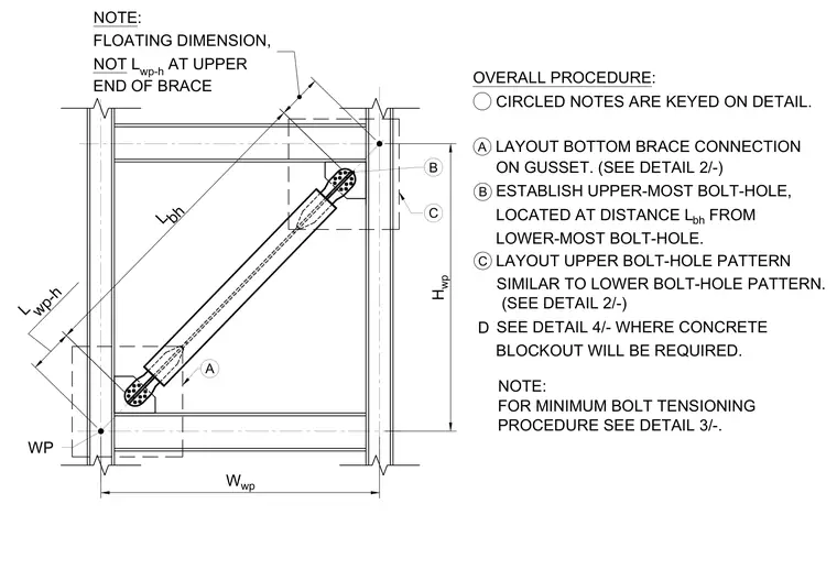
A structural detail presents the layout procedure for bolt holes on a braced frame connection using gusset plates. The upper-most bolt-hole is established at distance L_bh from the lower-most bolt-hole, following a floating dimension rather than L_wp-h at the upper end of the brace. The upper bolt-hole pattern is laid out similar to the lower pattern, with reference notes coordinating with related connection details and concrete blockout locations. The overall procedure details the sequence for establishing bolt-hole patterns and minimum bolt tensioning requirements.
CIRCLED NOTES ARE KEYED ON DETAIL. A LAYOUT BOTTOM BRACE CONNECTION OVERALL PROCEDURE: B ESTABLISH UPPER-MOST BOLT-HOLE, C LAYOUT UPPER BOLT-HOLE PATTERN FOR MINIMUM BOLT TENSIONING LOCATED AT DISTANCE L bh FROM SIMILAR TO LOWER BOLT-HOLE PATTERN. PROCEDURE SEE DETAIL 3/-. ON GUSSET. (SEE DETAIL 2/-) WP L bh L wp-h NOTE: FLOATING DIMENSION, NOT L wp-h AT UPPER END OF BRACE B W wp H wp LOWER-MOST BOLT-HOLE. (SEE DETAIL 2/-) C A NOTE: SEE DETAIL 4/- WHERE CONCRETE BLOCKOUT WILL BE REQUIRED. D
Members view this detail in full resolution, download the CAD files (SVG, PDF), and can adapt it in the built-in CAD editor — export DXF, DWG, or PDF.
Start membership