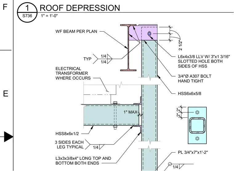
An electrical transformer is supported by an HSS8x6x1/2 framing member that connects back to an HSS6x6x5/8 column using top and bottom L3x3x3/8 angles, four inches long, welded with a quarter-inch fillet weld on three sides of each leg. Above this, a wide-flange beam per plan ties into the HSS column using L6x4x3/8 long-leg vertical angles featuring a three-inch by one-and-three-sixteenths slotted hole on both sides, secured with three-quarter-inch diameter A307 bolts hand-tightened. The HSS column base plate measures three-quarters by seven inches by one foot two inches and is welded with a quarter-inch fillet weld. A one-inch maximum clearance is maintained at the framing connection where the transformer occurs.
2 1/2" 2 1/2" 2" 2" 1" MAX 1/4 1/4 1/4 TYP 1/4 3 SIDES EACH LEG TYPICAL WF BEAM PER PLAN HSS8x6x1/2 ELECTRICAL TRANSFORMER WHERE OCCURS L3x3x3/8x4" LONG TOP AND BOTTOM BOTH ENDS L6x4x3/8 LLV W/ 3"x1 3/16" SLOTTED HOLE BOTH SIDES OF HSS 3/4"Ø A307 BOLT HAND TIGHT HSS6x6x5/8 PL 3/4"x7"x1'-2" E F 1" = 1'-0" S736 1 ROOF DEPRESSION
Members view this detail in full resolution, download the CAD files (SVG, PDF), and can adapt it in the built-in CAD editor — export DXF, DWG, or PDF.
Start membership