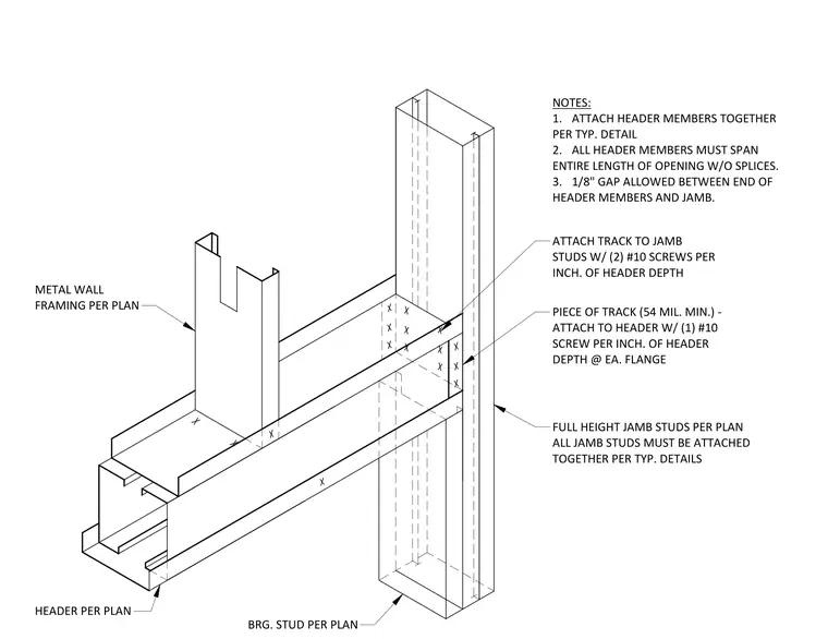
This assembly consists of a cold-formed steel header supported by full-height jamb studs. The header members must span the entire length of the opening without splices, with a maximum one-eighth inch gap allowed between the header ends and the jamb. A piece of track with a minimum thickness of fifty-four mils is attached to the header using one number ten screw per inch of header depth at each flange. The track is further secured to the jamb studs using two number ten screws per inch of header depth. All jamb studs must be attached together according to typical project details.
ATTACH TRACK TO JAMB STUDS W/ (2) #10 SCREWS PER INCH. OF HEADER DEPTH PIECE OF TRACK (54 MIL. MIN.) - ATTACH TO HEADER W/ (1) #10 SCREW PER INCH. OF HEADER DEPTH @ EA. FLANGE FULL HEIGHT JAMB STUDS PER PLAN ALL JAMB STUDS MUST BE ATTACHED TOGETHER PER TYP. DETAILS HEADER PER PLAN NOTES: 1. ATTACH HEADER MEMBERS TOGETHER PER TYP. DETAIL 2. ALL HEADER MEMBERS MUST SPAN ENTIRE LENGTH OF OPENING W/O SPLICES. 3. 1/8" GAP ALLOWED BETWEEN END OF HEADER MEMBERS AND JAMB. METAL WALL FRAMING PER PLAN BRG. STUD PER PLAN
Members view this detail in full resolution, download the CAD files (SVG, PDF), and can adapt it in the built-in CAD editor — export DXF, DWG, or PDF.
Start membership