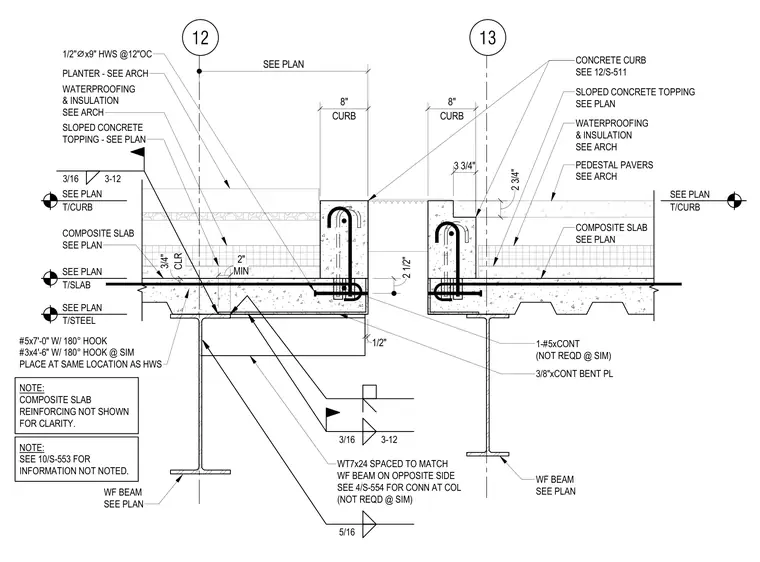
A concrete planter curb assembly situated between two composite metal deck slabs supported by wide flange steel beams. The curb features an eight-inch thickness and is reinforced with continuous number five bars and number three hooked bars placed at twelve-inch intervals, matching the spacing of half-inch diameter by nine-inch headed stud anchors. A continuous three-eighths-inch bent plate welded with three-sixteenths-inch fillet welds spans between the wide flange beams, with a WT7x24 section spaced to match the opposite beam. The assembly includes pedestal pavers, waterproofing, insulation, and a sloped concrete topping coordinated with architectural drawings. Clearances and elevations are referenced to the top of the curb, slab, and steel as shown on plan.
12 13 T/CURB SEE PLAN 1/2" ⌀ x9" HWS @12"OC COMPOSITE SLAB SEE PLAN 3/16 3-12 T/SLAB SEE PLAN T/STEEL SEE PLAN 3/8"xCONT BENT PL WT7x24 SPACED TO MATCH WF BEAM ON OPPOSITE SIDE SEE 4/S-554 FOR CONN AT COL (NOT REQD @ SIM) 3/16 3-12 5/16 1-#5xCONT (NOT REQD @ SIM) WF BEAM SEE PLAN WF BEAM SEE PLAN #5x7'-0" W/ 180° HOOK #3x4'-6" W/ 180° HOOK @ SIM PLACE AT SAME LOCATION AS HWS CONCRETE CURB SEE 12/S-511 SLOPED CONCRETE TOPPING SEE PLAN WATERPROOFING & INSULATION SEE ARCH PEDESTAL PAVERS SEE ARCH COMPOSITE SLAB SEE PLAN NOTE: COMPOSITE SLAB REINFORCING NOT SHOWN FOR CLARITY. NOTE: SEE 10/S-553 FOR INFORMATION NOT NOTED. PLANTER - SEE ARCH WATERPROOFING & INSULATION SEE ARCH SLOPED CONCRETE TOPPING - SEE PLAN SEE PLAN CURB 8" T/CURB SEE PLAN MIN 2" CLR 3/4" 2 1/2" 1/2" 2 3/4" 3 3/4" CURB 8"
Members view this detail in full resolution, download the CAD files (SVG, PDF), and can adapt it in the built-in CAD editor — export DXF, DWG, or PDF.
Start membership