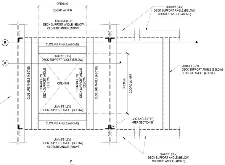
The framing assembly for the roof opening consists of L6x4x3/8 long-leg-vertical deck support angles positioned below the deck and closure angles positioned above. A typical L2x2 angle is provided at the corners for additional support. All opening dimensions must be coordinated with the mechanical unit manufacturer and verified against mechanical, electrical, and plumbing drawings prior to fabrication. The contractor is responsible for providing all necessary shop drawings and structural calculations for the framing assembly.
OPENING A PLAN VIEW L6x4x3/8 (LLV) DECK SUPPORT ANGLE (BELOW) L6x4x3/8 (LLV) DECK SUPPORT ANGLE (BELOW) L6x4x3/8 (LLV) DECK SUPPORT ANGLE (BELOW) COORD W/ MFR OPENING COORD W/ MFR OPENING L6x4x3/8 (LLV) DECK SUPPORT ANGLE (BELOW) CLOSURE ANGLE (ABOVE) CLOSURE ANGLE (ABOVE) B L6x4x3/8 (LLV) DECK SUPPORT ANGLE (BELOW) CLOSURE ANGLE (ABOVE) CLOSURE ANGLE (ABOVE) L6x4x3/8 (LLV) DECK SUPPORT ANGLE (BELOW) CLOSURE ANGLE (ABOVE) CLOSURE ANGLE (ABOVE) L6x4x3/8 (LLV) DECK SUPPORT ANGLE (BELOW) CLOSURE ANGLE (ABOVE) L6x4x3/8 (LLV) DECK SUPPORT ANGLE (BELOW) CLOSURE ANGLE (ABOVE) L2x2 ANGLE (TYP) ~REF SECTION B L6x4x3/8 (LLV) DECK SUPPORT ANGLE (BELOW) CLOSURE ANGLE (ABOVE) NOTES: 1. VERIFY ALL DIMENSIONS WITH MECHANICAL UNIT SUPPLIER AND MEP DRAWINGS PRIOR TO FABRICATION 2. CONTRACTOR SHALL PROVIDE DRAWINGS AND CALCULATIONS
Members view this detail in full resolution, download the CAD files (SVG, PDF), and can adapt it in the built-in CAD editor — export DXF, DWG, or PDF.
Start membership