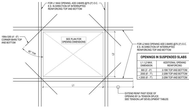
Reinforcement layout for rectangular penetrations in suspended concrete slabs utilizing interrupted reinforcing bars aligned with the opening dimensions L1 and L2. Additional reinforcing bars are placed top and bottom on each side at seventy-five millimeters on center, with sizing determined by opening dimensions ranging from fifteen-millimeter bars for openings up to nine hundred millimeters, twenty-millimeter bars up to two thousand millimeters, and twenty-five-millimeter bars for larger openings. Forty-five-degree diagonal corner bars measuring fifteen millimeters by twelve hundred millimeters are positioned at all four corners top and bottom. All supplemental reinforcement extends past the edge of the opening by twice the tension lap splice length per tension lap development tables.
L1 L2 FOR L1 MAX OPENING, ADD 2-BARS @75 (3") O.C. E.S. IN DIRECTION OF INTERRUPTED REINFORCING TOP AND BOTTOM FOR L2 MAX OPENING ADD 2-BARS @75 (3") O.C. E.S. IN DIRECTION OF INTERRUPTED REINFORCING TOP AND BOTTOM EXTEND REINF PAST EDGE OF OPENING BY 2x TENSION SPLICE. SEE TENSION LAP DEVELOPMENT TABLES 15Mx1200 (4' - 0") CORNER BARS TOP AND BOTTOM SEE PLAN FOR OPENING DIMENSIONS 80 OPENINGS IN SUSPENDED SLABS L1 / L2 MAX. DIMENSION 900 (3' - 0") ADDITIONAL OPENING REINFORCING 2-15M TOP AND BOTTOM 2000 (6' - 7") > 2000 (6' - 7") 2-20M TOP AND BOTTOM 2-25M TOP AND BOTTOM 45° TYP.
Members view this detail in full resolution, download the CAD files (SVG, PDF), and can adapt it in the built-in CAD editor — export DXF, DWG, or PDF.
Start membership