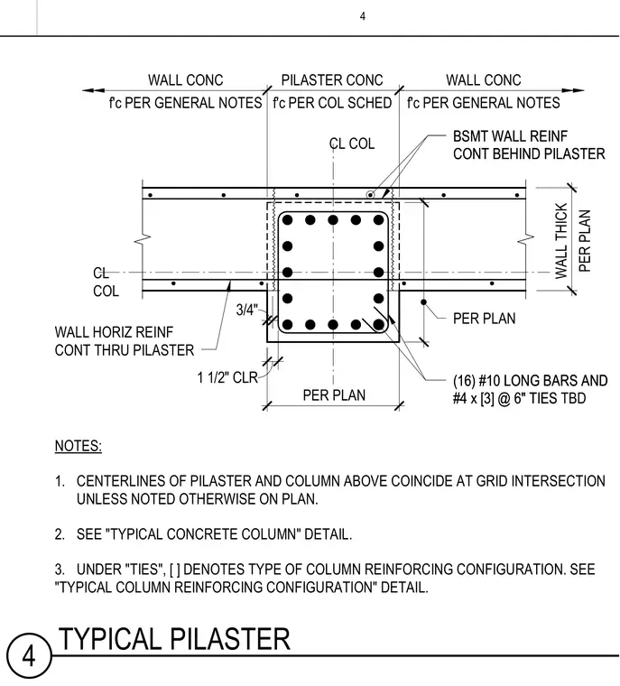
This structural plan detail shows a concrete pilaster integrated into a basement wall with a specified concrete compressive strength per the column schedule and general notes. The assembly features sixteen number ten longitudinal reinforcing bars tied with number four ties spaced at six inches on center. The horizontal wall reinforcing continues through the pilaster while the basement wall reinforcing continues behind it, maintaining structural continuity. Dimensions indicate a one and one-half inch concrete clearance and centerlines aligned with the column grid intersections.
NOTES: 1. CENTERLINES OF PILASTER AND COLUMN ABOVE COINCIDE AT GRID INTERSECTION UNLESS NOTED OTHERWISE ON PLAN. 2. SEE "TYPICAL CONCRETE COLUMN" DETAIL. 3. UNDER "TIES", [ ] DENOTES TYPE OF COLUMN REINFORCING CONFIGURATION. SEE "TYPICAL COLUMN REINFORCING CONFIGURATION" DETAIL. 1 1/2" CLR 3/4" 18" 19" 14" 18" PILASTER CONC PER PLAN WALL THICK PER PLAN WALL CONC WALL CONC CL COL CL COL (16) #10 LONG BARS AND #4 x [3] @ 6" TIES (16) #10 LONG BARS AND #4 x [3] @ 6" TIES TBD WALL HORIZ REINF CONT THRU PILASTER BSMT WALL REINF CONT BEHIND PILASTER BSMT WALL REINF CONT BEHIND PILASTER f'c PER COL SCHED f'c PER GENERAL NOTES f'c PER GENERAL NOTES PER PLAN 4 4 TYPICAL PILASTER
Members view this detail in full resolution, download the CAD files (SVG, PDF), and can adapt it in the built-in CAD editor — export DXF, DWG, or PDF.
Start membership