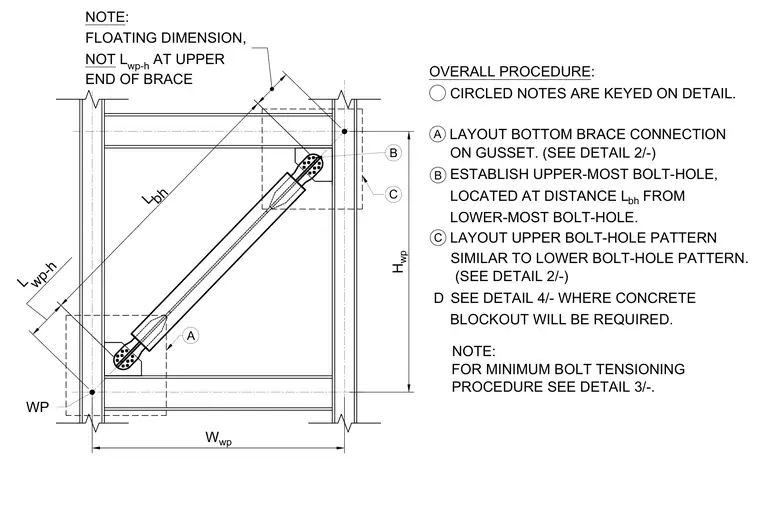
This structural detail outlines the sequence and dimensional layout for bolting a braced frame connection between structural steel columns, beams, and gusset plates. The procedure establishes the upper-most bolt-hole at a defined distance from the lower-most bolt-hole, maintaining a floating dimension along the brace axis rather than tying directly to the work point. Additional sequential steps reference the layout of the bottom brace connection, similar upper bolt-hole patterns, and required concrete blockouts. Reference notes dictate minimum bolt tensioning procedures and coordinate related connection details.
CIRCLED NOTES ARE KEYED ON DETAIL. A LAYOUT BOTTOM BRACE CONNECTION OVERALL PROCEDURE: B ESTABLISH UPPER-MOST BOLT-HOLE, C LAYOUT UPPER BOLT-HOLE PATTERN FOR MINIMUM BOLT TENSIONING LOCATED AT DISTANCE L bh FROM SIMILAR TO LOWER BOLT-HOLE PATTERN. PROCEDURE SEE DETAIL 3/-. ON GUSSET. (SEE DETAIL 2/-) WP L bh L wp-h NOTE: FLOATING DIMENSION, NOT L wp-h AT UPPER END OF BRACE B W wp H wp LOWER-MOST BOLT-HOLE. (SEE DETAIL 2/-) C A NOTE: SEE DETAIL 4/- WHERE CONCRETE BLOCKOUT WILL BE REQUIRED. D
Members view this detail in full resolution, download the CAD files (SVG, PDF), and can adapt it in the built-in CAD editor — export DXF, DWG, or PDF.
Start membership