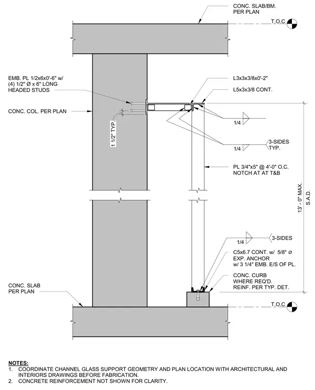
Head and sill support assembly for channel glass installed adjacent to a concrete column and floor slab. The head condition utilizes a continuous L5x3x3/8 angle welded with a quarter-inch fillet weld on three sides, tied back to a half-inch by six-inch by six-inch embedded steel plate with four half-inch diameter by six-inch long headed studs cast into the concrete column. An L3x3x3/8 by two-inch angle and intermittent three-quarter-inch by five-inch plates spaced at four feet on center with top and bottom notches secure the glass framing. The sill condition bears on a concrete curb with a continuous C5x6.7 structural channel anchored by five-eighth-inch diameter expansion anchors with three and a quarter inches of embedment.
T.O.C NOTES: 1. COORDINATE CHANNEL GLASS SUPPORT GEOMETRY AND PLAN LOCATION WITH ARCHITECTURAL AND INTERIORS DRAWINGS BEFORE FABRICATION. 2. CONCRETE REINFORCEMENT NOT SHOWN FOR CLARITY. T.O.C 1 1/2" TYP. S.A.D. 13' - 0" MAX. CONC. SLAB PER PLAN CONC. CURB WHERE REQ'D. REINF. PER TYP. DET. C5x6.7 CONT. w/ 5/8" ⌀ EXP. ANCHOR w/ 3 1/4" EMB. E/S OF PL. 3-SIDES 1/4 PL 3/4"x5" @ 4'-0" O.C. NOTCH AT AT T&B 3-SIDES TYP. 1/4 1/4 L5x3x3/8 CONT. L3x3x3/8x0'-2" CONC. SLAB/BM. PER PLAN EMB. PL 1/2x6x0'-6" w/ (4) 1/2" Ø x 6" LONG HEADED STUDS CONC. COL. PER PLAN
Members view this detail in full resolution, download the CAD files (SVG, PDF), and can adapt it in the built-in CAD editor — export DXF, DWG, or PDF.
Start membership