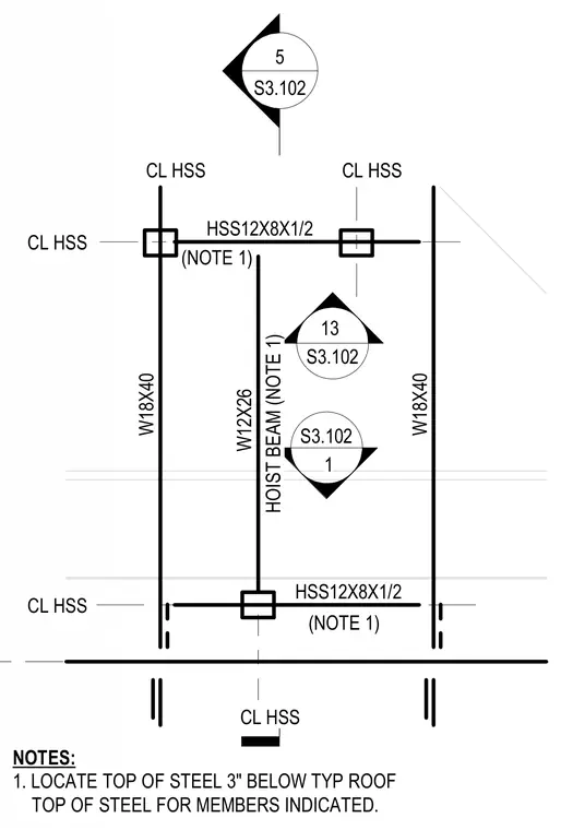
This structural framing plan details a roof-level equipment and hoist beam arrangement utilizing W18x40 edge members, HSS12x8x1/2 structural steel members, and a central W12x26 hoist beam. Specific members are positioned with their top of steel located three inches below the typical roof top of steel per structural notes. Centerlines of the hollow structural sections are explicitly aligned with supporting framing.
S3.102 S3.102 13 1 HSS12X8X1/2 W18X40 W18X40 W12X26 5 S3.102 HOIST BEAM (NOTE 1) CL HSS CL HSS CL HSS HSS12X8X1/2 (NOTE 1) (NOTE 1) NOTES: 1. LOCATE TOP OF STEEL 3" BELOW TYP ROOF TOP OF STEEL FOR MEMBERS INDICATED. CL HSS CL HSS S3.102 S3.102 13 1 HSS12X8X1/2 W18X40 W18X40 W12X26 5 S3.102 HOIST BEAM (NOTE 1) CL HSS CL HSS CL HSS HSS12X8X1/2 (NOTE 1) (NOTE 1) NOTES: 1. LOCATE TOP OF STEEL 3" BELOW TYP ROOF TOP OF STEEL FOR MEMBERS INDICATED. CL HSS CL HSS
Members view this detail in full resolution, download the CAD files (SVG, PDF), and can adapt it in the built-in CAD editor — export DXF, DWG, or PDF.
Start membership