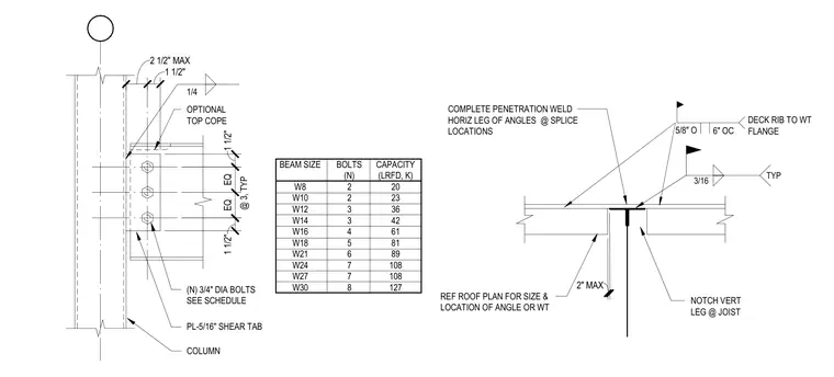
A roof subdiaphragm connection utilizes structural angles or WT shapes welded to deck ribs, alongside a single plate shear tab connection at a steel column. The subdiaphragm detail specifies complete penetration welds at horizontal legs of angles at splice locations, with vertical legs notched at joists and connected to deck ribs using five-eighths-inch diameter fasteners at six inches on center. The beam-to-column connection consists of a five-sixteenths-inch thick shear tab welded to the column flange and fastened to the supported beam web with three-quarter-inch diameter bolts, with bolt counts and LRFD capacities varying by beam size from W8 to W30.
NOTCH VERT LEG @ JOIST REF ROOF PLAN FOR SIZE & LOCATION OF ANGLE OR WT 3/16 TYP COMPLETE PENETRATION WELD HORIZ LEG OF ANGLES @ SPLICE LOCATIONS 2" MAX DECK RIB TO WT FLANGE 5/8" O 6" OC BEAM SIZE W8 W10 W12 W14 W16 W18 W21 W24 W27 W30 BOLTS (N) 2 2 3 3 4 5 6 7 7 8 CAPACITY (LRFD, K) 20 23 36 42 61 81 89 108 108 127 1/4 2 1/2" MAX 1 1/2" COLUMN (N) 3/4" DIA BOLTS SEE SCHEDULE PL-5/16" SHEAR TAB EQ EQ OPTIONAL TOP COPE 1 1/2" 1 1/2" @ 3, TYP
Members view this detail in full resolution, download the CAD files (SVG, PDF), and can adapt it in the built-in CAD editor — export DXF, DWG, or PDF.
Start membership