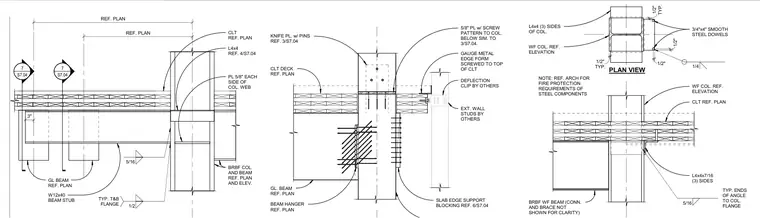
A wide flange cantilever steel beam with a W12x40 beam stub connects to a wide flange column utilizing top and bottom flange welds and five-eighths inch plates on each side of the column web. A cross-laminated timber deck bears on the assembly alongside glued-laminated timber beams, tied with knife plates with pins and structural steel angles sized L4x4. Additional detailing includes three-quarter by four-inch smooth steel dowels, a gauge metal edge form screwed to the top of the timber deck, slab edge support blocking, and exterior wall studs with deflection clips by others. A reference note directs coordination with architectural drawings for fire protection requirements of steel components.
L4x4x7/16 (3) SIDES 3/4"x4" SMOOTH STEEL DOWELS 1/4 1/2" 1/2" TYP. 1/2" TYP. 1/2" 5/16 TYP. ENDS OF ANGLE TO COL. FLANGE WF COL. REF. ELEVATION L4x4 (3) SIDES OF COL. PLAN VIEW WF COL. REF. ELEVATION NOTE: REF. ARCH FOR FIRE PROTECTION REQUIREMENTS OF STEEL COMPONENTS CLT REF. PLAN BRBF WF BEAM (CONN. AND BRACE NOT SHOWN FOR CLARITY) BEAM HANGER REF. PLAN CLT DECK REF. PLAN KNIFE PL. w/ PINS REF. 3/S7.04 GL. BEAM REF. PLAN SLAB EDGE SUPPORT BLOCKING REF. 6/S7.04 5/8" PL w/ SCREW PATTERN TO COL. BELOW SIM. TO 3/S7.04. EXT. WALL STUDS BY OTHERS DEFLECTION CLIP BY OTHERS GAUGE METAL EDGE FORM SCREWED TO TOP OF CLT 3" BRBF COL. AND BEAM REF. PLAN AND ELEV. PL 5/8" EACH SIDE OF COL. WEB L4x4 REF. 4/S7.04 GL BEAM REF. PLAN W12x40 BEAM STUB CLT REF. PLAN REF. PLAN REF. PLAN 7 S7.04 _____ 7 S7.04 _____ 5/16 1/2 TYP. T&B FLANGE
Members view this detail in full resolution, download the CAD files (SVG, PDF), and can adapt it in the built-in CAD editor — export DXF, DWG, or PDF.
Start membership