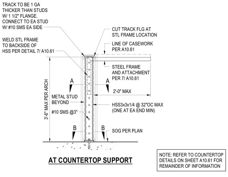
This wall section details a counter support assembly featuring vertical hollow structural section members spaced at a maximum of thirty-two inches on center behind metal stud framing. The cold-formed steel track is specified one gauge thicker than the studs with one-and-a-half-inch flanges, fastened to each stud with number ten sheet metal screws on each side. A steel frame supports the casework up to two feet maximum width, with the track flange cut at the steel frame location and welded to the backside of the hollow structural section. The wall assembly anchors to the slab on grade, with metal studs extending vertically up to a maximum of three feet six inches per architecture.
3'-6" MAX PER ARCH A A B B HSS3x3x1/4 @ 32"OC MAX (ONE AT EA END MIN) AT COUNTERTOP SUPPORT METAL STUD BEYOND #10 SMS @3" STEEL FRAME AND ATTACHMENT PER 7/ A10.61 2'-0" MAX CUT TRACK FLG AT STL FRAME LOCATION LINE OF CASEWORK PER A10.61 WELD STL FRAME TO BACKSIDE OF HSS PER DETAIL 7/ A10.61 TRACK TO BE 1 GA THICKER THAN STUDS W/ 1 1/2" FLANGE. CONNECT TO EA STUD W/ #10 SMS EA SIDE SOG PER PLAN NOTE: REFER TO COUNTERTOP DETAILS ON SHEET A10.61 FOR REMAINDER OF INFORMATION
Members view this detail in full resolution, download the CAD files (SVG, PDF), and can adapt it in the built-in CAD editor — export DXF, DWG, or PDF.
Start membership