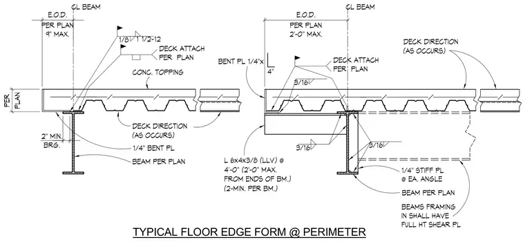
The assembly features a concrete topping over a metal deck supported by a perimeter beam per plan, with edge of deck extending up to nine inches maximum or two feet maximum depending on framing conditions. A one-quarter-inch bent plate acts as the edge form, welded with three-sixteenth-inch fillet welds, while a continuous angle measuring six by four by three-eighths is spaced at four feet on center with a two-foot maximum from the ends of the beam. A one-quarter-inch stiffener plate is welded to each angle, and beams framing in require a full height shear plate. Deck attachment follows project specifications, maintaining a two-inch minimum bearing on the supporting steel flange.
PER PLAN 2" MIN. BRG. E.O.D. PER PLAN 9" MAX. E.O.D. PER PLAN 2'-0" MAX. TYPICAL FLOOR EDGE FORM @ PERIMETER 1 1/2-12 1/8 BEAM PER PLAN 1/4" BENT PL 4" CL BEAM 3/16 3/16 3/16 CL BEAM DECK ATTACH PER PLAN DECK ATTACH PER PLAN BEAMS FRAMING IN SHALL HAVE FULL HT SHEAR PL DECK DIRECTION (AS OCCURS) CONC. TOPPING DECK DIRECTION (AS OCCURS) BEAM PER PLAN 1/4" STIFF PL @ EA. ANGLE BENT PL 1/4"x L 6x4x3/8 (LLV) @ 4'-0" (2'-0" MAX. FROM ENDS OF BM.) (2-MIN. PER BM.)
Members view this detail in full resolution, download the CAD files (SVG, PDF), and can adapt it in the built-in CAD editor — export DXF, DWG, or PDF.
Start membership