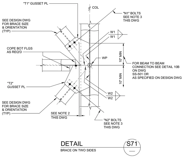
A steel brace connection occurs on two sides of a column with intersecting gusset plates. The assembly utilizes welded connections designated as W1 and W2 along with bolted connections using N1 and N2 bolts sized per the drawing notes. Bottom flanges of the connecting beams are coped as required to clear the gusset plates and column flange. A minimum clearance of ten inches is maintained for the connection geometry, with brace sizes and orientations determined by design drawings.
BRACE ON TWO SIDES THIS DWG WP W2 W2 W1 W1 COL DETAIL S71 "N1" BOLTS SEE NOTE 3 THIS DWG "N2" BOLTS SEE NOTE 3 THIS DWG COPE BOT FLGS AS REQ'D SEE NOTE 2 "T1" GUSSET PL SEE DESIGN DWG FOR BRACE SIZE & ORIENTATION (TYP) "T2" GUSSET PL SEE DESIGN DWG FOR BRACE SIZE & ORIENTATION (TYP) FOR BEAM TO BEAM CONNECTION SEE DETAIL 10B ON DWG SS-501 OR AS SPECIFIED ON DESIGN DWG 10" MIN 10" MIN
Members view this detail in full resolution, download the CAD files (SVG, PDF), and can adapt it in the built-in CAD editor — export DXF, DWG, or PDF.
Start membership