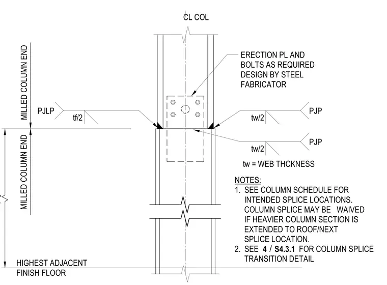
A typical non-frame column splice joins an upper steel column section to a lower steel column section. Both meeting column ends are milled and bear directly against one another above the highest adjacent finish floor. An erection plate is secured with temporary or permanent bolts as required, with the connection design delegated to the steel fabricator. Partial-joint-penetration welds are specified at the flange and web connections, where the weld depth is proportioned to the flange thickness and web thickness.
4'-0" ERECTION PL AND BOLTS AS REQUIRED DESIGN BY STEEL FABRICATOR NOTES: 1. SEE COLUMN SCHEDULE FOR INTENDED SPLICE LOCATIONS. COLUMN SPLICE MAY BE WAIVED IF HEAVIER COLUMN SECTION IS EXTENDED TO ROOF/NEXT SPLICE LOCATION. 2. SEE FOR COLUMN SPLICE TRANSITION DETAIL CL COL tw = WEB THCKNESS HIGHEST ADJACENT FINISH FLOOR MILLED COLUMN END MILLED COLUMN END tw/2 PJP tw/2 PJP tf/2 PJLP / 4 S4.3.1
Members view this detail in full resolution, download the CAD files (SVG, PDF), and can adapt it in the built-in CAD editor — export DXF, DWG, or PDF.
Start membership