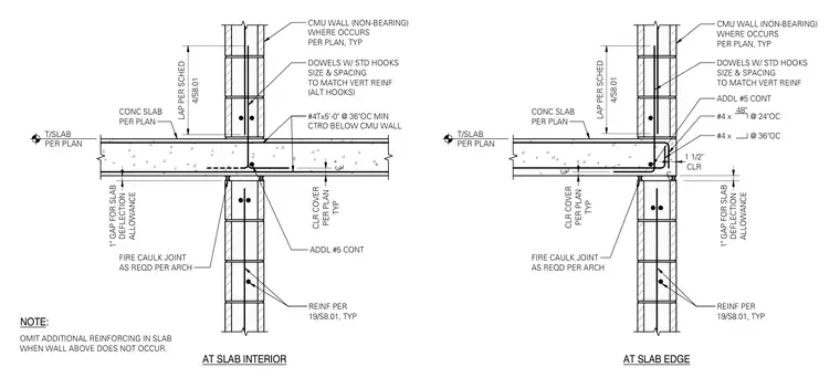
A concrete slab connects to non-bearing concrete masonry unit walls at both interior and slab edge conditions. The assembly incorporates standard hook dowels sized and spaced to match the vertical reinforcement, supplemented by continuous number five reinforcing bars. A one-inch deflection gap is maintained with fire caulking at the joint as required by architecture. Additional slab reinforcing includes number four bars at thirty-six inches on center centered below the interior CMU wall, and alternating number four bars at twenty-four and thirty-six inches on center at the slab edge. A note specifies to omit additional slab reinforcing when the wall above does not occur.
CMU WALL (NON-BEARING) WHERE OCCURS PER PLAN, TYP CONC SLAB PER PLAN DOWELS W/ STD HOOKS SIZE & SPACING TO MATCH VERT REINF (ALT HOOKS) ADDL #5 CONT 4/S8.01 LAP PER SCHED ALLOWANCE 1" GAP FOR SLAB DEFLECTION T/SLAB PER PLAN FIRE CAULK JOINT AS REQD PER ARCH C L TYP CLR COVER PER PLAN REINF PER 19/S8.01, TYP AT SLAB INTERIOR CMU WALL (NON-BEARING) WHERE OCCURS PER PLAN, TYP CONC SLAB PER PLAN DOWELS W/ STD HOOKS SIZE & SPACING TO MATCH VERT REINF FIRE CAULK JOINT AS REQD PER ARCH ALLOWANCE 1" GAP FOR SLAB DEFLECTION T/SLAB PER PLAN REINF PER 19/S8.01, TYP AT SLAB EDGE C L TYP CLR COVER PER PLAN 4/S8.01 LAP PER SCHED ADDL #5 CONT C L CLR 1 1/2" NOTE: OMIT ADDITIONAL REINFORCING IN SLAB WHEN WALL ABOVE DOES NOT OCCUR. #4Tx5'-0" @ 36"OC MIN CTRD BELOW CMU WALL #4 x @ 24"OC 48" #4 x @ 36"OC
Members view this detail in full resolution, download the CAD files (SVG, PDF), and can adapt it in the built-in CAD editor — export DXF, DWG, or PDF.
Start membership