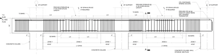
A reinforced concrete beam spans between concrete columns with top and bottom longitudinal reinforcing bars and transverse stirrups. Stirrups are spaced at four inches on center over the required splice lengths. Zone one and zone two regions divide the span into thirds, with specific bar development lengths and spacings defined by member dimensions. Standard hooks or T-headed terminators are provided at the ends of longitudinal bars where indicated. Splices are located at the span and support centerlines per structural requirements.
L C L C L C T.O. PLAN SLAB EL.=SEE OF SUPPORT OF SPAN & SPLICE IF REQUIRED IF REQUIRED OF SPAN & SPLICE PROVIDE STIRRUPS @ 4" OC OVER SPLICE LENGTH T2 BARS CONCRETE COLUMN CONCRETE COLUMN CONCRETE COLUMN, WALL OR BEAM, SEE PLAN 'd2' 2" 4X'd2' 2" ZONE 1 L1 SPAN L/3 ZONE 1 ZONE 2 2" L/3 4X'd2' 4X'd2' L/3 ZONE 2 ZONE 1 L/3 L1 SPAN ZONE 1 2" 4X'd2' 2" L/3 L/3 L/3 PROVIDE STD HK @ ENDS OF LONGIT BARS OR T-HEADED TERMINATOR A A COL CONTINUES WHERE OOCURS T2 BARS B2 BARS B2 BARS PROVIDE STIRRUPS @ 4" OC OVER SPLICE LENGTH L C OF SUPPORT L C OF SUPPORT
Members view this detail in full resolution, download the CAD files (SVG, PDF), and can adapt it in the built-in CAD editor — export DXF, DWG, or PDF.
Start membership