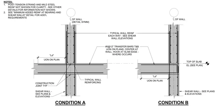
Intersection conditions between a concrete shear wall and a concrete slab for both Condition A and Condition B. Typical wall reinforcing runs vertically on each face, tied into construction joints at the slab levels. Number 5 transfer bars at 12 inches spacing are placed top and bottom unless noted otherwise on plans, centered at the wall and hooked at the slab edge where applicable. Development lengths are specified as Ld unless noted otherwise on plan, and post-tension strand and mild steel reinforcement are omitted from the main view for clarity.
NOTES: 1. POST-TENSION STRAND AND MILD STEEL REINF NOT SHOWN FOR CLARITY - SEE OTHER DETAILS FOR INFORMATION NOT SHOWN. 2. SEE "MINIMUM ADDED REINF AT BEARING AND SHEAR WALLS" DETAIL FOR ADD'L REQUIREMENTS OF WALL (DETAIL SYMM) OF WALL CONDITION A CONDITION B TYPICAL WALL REINF EACH WAY - SEE SHEAR WALL ELEVATIONS CONSTRUCTION JOINT TYP SHEAR WALL - SEE PLANS & ELEVATIONS TYPICAL WALL REINFORCING SHEAR WALL - SEE PLANS & ELEVATIONS #5@12" TRANSFER BARS T&B UON ON PLANS. CENTER AT WALL. HOOK AT SLAB EDGE - WHERE OCCURS EL (SEE PLAN) TOP OF SLAB UON ON PLAN "Ld" UON ON PLAN "Ld"
Members view this detail in full resolution, download the CAD files (SVG, PDF), and can adapt it in the built-in CAD editor — export DXF, DWG, or PDF.
Start membership