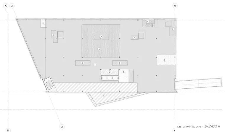
The plan illustrates the structural layout for level 3, indicating column lines, structural framing, and specific loading zones designated by numeric callouts. Hatched areas represent specialized load zones or openings across the floor plate. Gridlines K, J, and A establish the spatial coordinate system.
Text on the drawing
A K J J 1 5 5 4 3 5 4 5 2 10 7 5 7 9 7
Members view this detail in full resolution, download the CAD files (SVG, PDF), and open any detail in the built-in CAD editor to edit and export DXF or DWG.
Sign in to subscribe