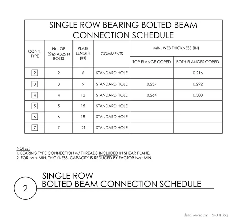
The schedule provides design parameters for steel beam connections utilizing 7/8-inch diameter A325-N bolts in standard holes. It lists connection types 2 through 7, specifying the number of bolts, plate lengths, comments, and minimum web thicknesses for conditions with top flange coped or both flanges coped. Engineering notes at the bottom clarify that the bearing type connection includes threads in the shear plane and provides a reduction factor if the web thickness is less than the minimum.
Text on the drawing
NOTES: 1. BEARING TYPE CONNECTION w/ THREADS INCLUDED IN SHEAR PLANE. 2. FOR tw < MIN. THICKNESS, CAPACITY IS REDUCED BY FACTOR tw/t MIN. SINGLE ROW BEARING BOLTED BEAM CONNECTION SCHEDULE CONN. TYPE No. OF 7 8 "Ø A325 N BOLTS PLATE LENGTH (IN) COMMENTS MIN. WEB THICKNESS (IN) TOP FLANGE COPED BOTH FLANGES COPED 2 6 STANDARD HOLE 0.216 3 9 STANDARD HOLE 0.237 0.292 4 12 STANDARD HOLE 0.264 0.300 5 15 STANDARD HOLE 6 18 STANDARD HOLE 7 21 STANDARD HOLE 2 3 4 5 6 7 2 SINGLE ROW BOLTED BEAM CONNECTION SCHEDULE
Members view this detail in full resolution, download the CAD files (SVG, PDF), and open any detail in the built-in CAD editor to edit and export DXF or DWG.
Sign in to subscribe