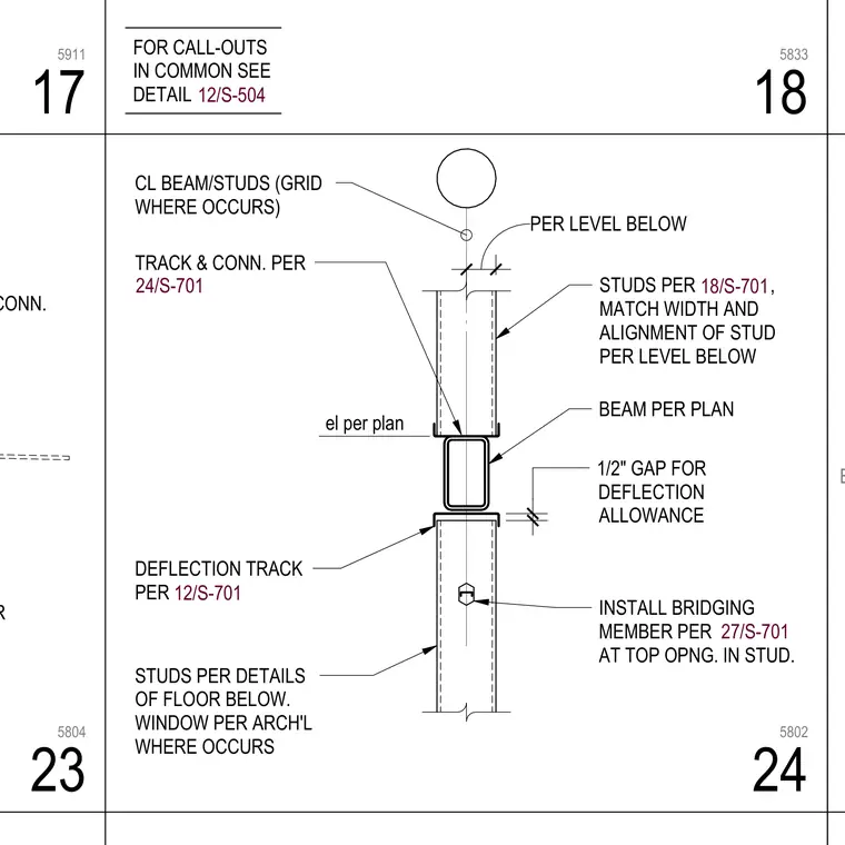
A horizontal beam per plan is positioned between upper and lower light-gauge metal studs. A deflection track with a one-half-inch gap is provided for deflection allowance. Stud widths and alignments match the level below, with bridging members installed at the top opening in the stud per structural details.
INSTALL BRIDGING MEMBER PER AT TOP OPNG. IN STUD. DEFLECTION TRACK PER 1/2" GAP FOR DEFLECTION ALLOWANCE TRACK & CONN. PER STUDS PER , MATCH WIDTH AND ALIGNMENT OF STUD PER LEVEL BELOW BEAM PER PLAN STUDS PER DETAILS OF FLOOR BELOW. WINDOW PER ARCH'L WHERE OCCURS PER LEVEL BELOW CL BEAM/STUDS (GRID WHERE OCCURS) 24/S-701 18/S-701 27/S-701 12/S-701 el per plan WINDOW/DOOR CANOPY AND CONN. FOR CALL-OUTS IN COMMON SEE DETAIL 12/S-504 B 24 5802 23 5804 18 5833 17 5911
Members view this detail in full resolution, download the CAD files (SVG, PDF), and can adapt it in the built-in CAD editor — export DXF, DWG, or PDF.
Start membership