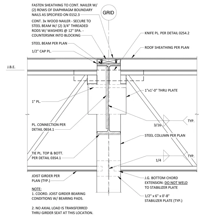
The assembly features a steel column supporting a steel beam, capped with a one-half inch thick cap plate. A continuous three-inch thick wood nailer is secured to the top of the steel beam using two three-quarter inch diameter threaded rods with washers spaced at twelve inches on center, with the rods countersunk into the blocking. Roof sheathing is fastened to this continuous nailer using two rows of diaphragm boundary nails as specified on sheet 01S2.3. A one-inch by one-foot through-plate connects the beam to the column, supplemented by a knife plate as detailed on 02S4.2. The connection includes a one-inch thick plate and a tie plate at the top and bottom as referenced on 03S4.1, with three-sixteenths inch typical fillet welds. A one-half inch by six-inch by eight-inch stabilizer plate is provided at the joist girder bottom chord extension, which is left unwelded to the stabilizer plate.
7 STEEL COLUMN PER PLAN 1" PL. 3/16 TYP. 1"x1'-0" THRU PLATE 1/2" CAP PL. STEEL BEAM PER PLAN ROOF SHEATHING PER PLAN PL. CONNECTION PER DETAIL 06S4.1 GRID CONT. 3x WOOD NAILER - SECURE TO STEEL BEAM W/ (2) 3/4" THREADED RODS W/ WASHERS @ 12" SPA. - COUNTERSINK INTO BLOCKING TIE PL. TOP & BOTT. FASTEN SHEATHING TO CONT. NAILER W/ (2) ROWS OF DIAPHRAGM BOUNDARY NAILS AS SPECIFIED ON 01S2.3 KNIFE PL. PER DETAIL 02S4.2
Members view this detail in full resolution, download the CAD files (SVG, PDF), and can adapt it in the built-in CAD editor — export DXF, DWG, or PDF.
Start membership