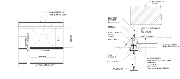
Roof framing conditions occur at a roof drain and equipment curb. The roof sheathing consists of three-quarter-inch CDX APA rated plywood fastened with ten-penny by zero-point-one-forty-eight-inch diameter screw shank nails spaced at four inches on center at edges and twelve inches on center intermediately. Openings are supported by double two-by framing members with minimum two-by-six framing beneath the roof drain location. An equipment curb by others sits atop a level platform supported by two-by-six or four-by-six number one members with Simpson "U" hangers, fastened with three three-eighths-inch diameter by five-inch lag screws on each side of the curb. A continuous two-by-four plate fastened with sixteen-penny nails at six inches on center staggered is provided alongside a cant strip above the roof sheathing. Steel truss purlins connect below using Simpson LTP4 connectors at twenty-four inches on center.
3/4" CDX APA RATED SHEATHING W/ 10dx0.148" ∅ SCREW SHANK NAILS EDGES: 4" O.C. INTM: 12" O.C. (EDGE BLOCKING IS NOT REQD) 2x6 #1 OR 4x6 #1 W/ SIMPSON "U" HANGER ROOF SHEATHING CANT STRIP PL 2x4 CONT W/ 16d @ 6"OC (STGRD) SEE PLAN EQUIP CURB BY OTHERS (3) 3/8" ∅ x 5" LAG SCREW @ EA SIDE OF CURB LEVEL PLATFORM TRUSS PURLIN EN NEW PROPOSED AC UNIT (S) LTP4 @ 24"OC SEE ARCH SEE ARCH (2) 2x6 MIN (2) 2x SUB-PURLIN SEE PLAN (TYP) WALL PANEL PER PLAN ROOF DRAIN SEE ARCH ROOF PURLIN (SEE PLAN WHERE OCCURS)
Members view this detail in full resolution, download the CAD files (SVG, PDF), and can adapt it in the built-in CAD editor — export DXF, DWG, or PDF.
Start membership