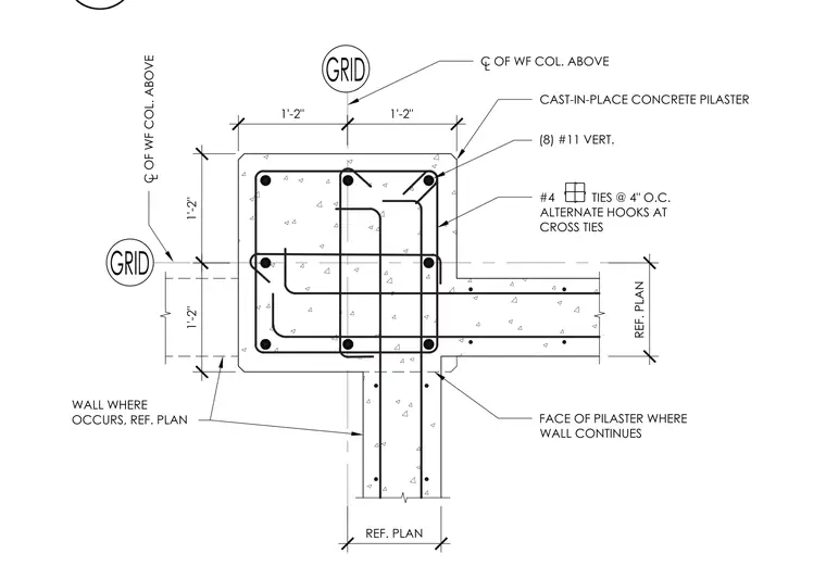
A cast-in-place concrete pilaster supports a wide-flange column above. The pilaster section incorporates eight number 11 vertical reinforcing bars and number four ties spaced at four inches on center with alternate hooks at cross ties. Dimensions indicate a symmetrically laid out column and wall intersection relative to the grid lines. The adjoining concrete wall continues from the face of the pilaster as referenced on plan.
REF. PLAN REF. PLAN 1'-2" 1'-2" 1'-2" 1'-2" C OF WF COL. ABOVE L L C OF WF COL. ABOVE FACE OF PILASTER WHERE WALL CONTINUES WALL WHERE OCCURS, REF. PLAN #4 TIES @ 4" O.C. ALTERNATE HOOKS AT CROSS TIES (8) #11 VERT. CAST-IN-PLACE CONCRETE PILASTER
Members view this detail in full resolution, download the CAD files (SVG, PDF), and can adapt it in the built-in CAD editor — export DXF, DWG, or PDF.
Start membership