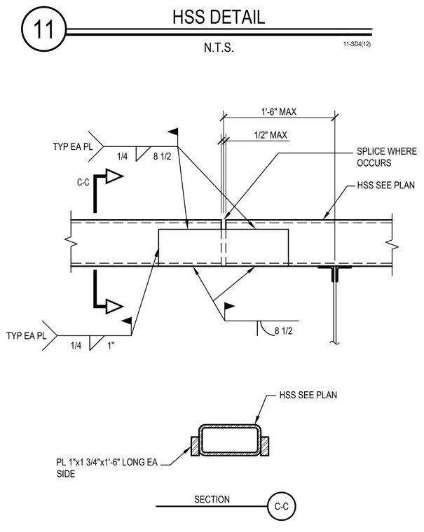
Two aligned hollow structural section members are joined end-to-end with a half-inch maximum gap where the splice occurs. Internal splice plates measuring 1 inch by 1 and 3/4 inches by 1 foot 6 inches long are placed on each side and secured with quarter-inch fillet welds typically on each plate. A one-half-inch maximum clearance is maintained between the abutting structural sections. Section C-C provides the placement of the side splice plates against the profile of the hollow structural section.
11 HSS DETAIL N.T.S. 11-SD4(12) 1/2" MAX SPLICE WHERE OCCURS HSS SEE PLAN HSS SEE PLAN C-C PL 1"x1 3/4"x1'-6" LONG EA SIDE C-C SECTION 1'-6" MAX 1/4 8 1/2 TYP EA PL 1/4 1" TYP EA PL 8 1/2
Members view this detail in full resolution, download the CAD files (SVG, PDF), and can adapt it in the built-in CAD editor — export DXF, DWG, or PDF.
Start membership