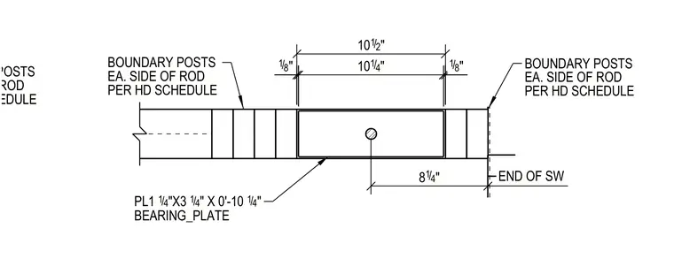
A bearing plate measuring one and one-quarter inches by three and one-quarter inches by ten and one-quarter inches is detailed with a central rod hole located eight and one-quarter inches from the end of the shear wall. Boundary posts are positioned on each side of the rod per the hold-down schedule. Dimensions indicate specific spacing of ten and one-half inches overall with one-eighth inch edge clearances.
END OF SW PER HD SCHEDULE EA. SIDE OF ROD BOUNDARY POSTS 18 / " PL1 1 4 / "X3 1 4 / " X 0'-10 1 4 / " BEARING_PLATE PER HD SCHEDULE EA. SIDE OF ROD BOUNDARY POSTS PER HD SCHEDULE EA. SIDE OF ROD BOUNDARY POSTS 18 / " 10 1 4 / " 10 1 2 / " 8 1 4 / "
Members view this detail in full resolution, download the CAD files (SVG, PDF), and can adapt it in the built-in CAD editor — export DXF, DWG, or PDF.
Start membership