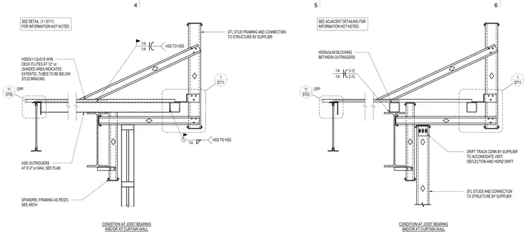
Outrigger and framing conditions at joist bearing and curtain wall interfaces. Hollow structural section outriggers sized HSS2x1-1/2x3/16 are positioned within deck flutes at 12 inches on center, supplemented by HSS outriggers at 6 feet on center maximum as indicated on the plan. HSS5x5x3/8 blocking is provided between outriggers. Steel stud framing and its connection to the structure are supplied by others, featuring drift track connections designed to accommodate vertical deflection and horizontal drift. Connections utilize quarter-inch fillet welds for hollow structural section to hollow structural section joints. Spandrel framing is provided as required per architectural drawings.
HSS OUTRIGGERS AT 6'-0" oc MAX, SEE PLAN SPANDREL FRAMING AS REQ'D, SEE ARCH HSS2x1-1/2x3/16 W/IN DECK FLUTES AT 12" oc (SHADED AREA INDICATES EXTENTS). TUBES TO BE BELOW STUD BRACING STL STUD FRAMING AND CONNECTION TO STRUCTURE BY SUPPLIER 1/4 HSS TO HSS 1/4 1/4 HSS TO HSS CONDITION AT JOIST BEARING AND/OR AT CURTAIN WALL SEE ADJACENT DETAILING FOR INFORMATION NOT NOTED. SEE DETAIL FOR INFORMATION NOT NOTED. / (1 S711) S711 1 S702 11 OPP STL STUDS AND CONNECTION TO STRUCTURE BY SUPPLIER DRIFT TRACK CONN BY SUPPLIER TO ACCOMODATE VERT DEFLECTION AND HORIZ DRIFT HSS5x5x3/8 BLOCKING BETWEEN OUTRIGGERS CONDITION AT JOIST BEARING AND/OR AT CURTAIN WALL S711 1 S702 11 OPP 1/4 1/4 3-12 3-12 6 5 4
Members view this detail in full resolution, download the CAD files (SVG, PDF), and can adapt it in the built-in CAD editor — export DXF, DWG, or PDF.
Start membership