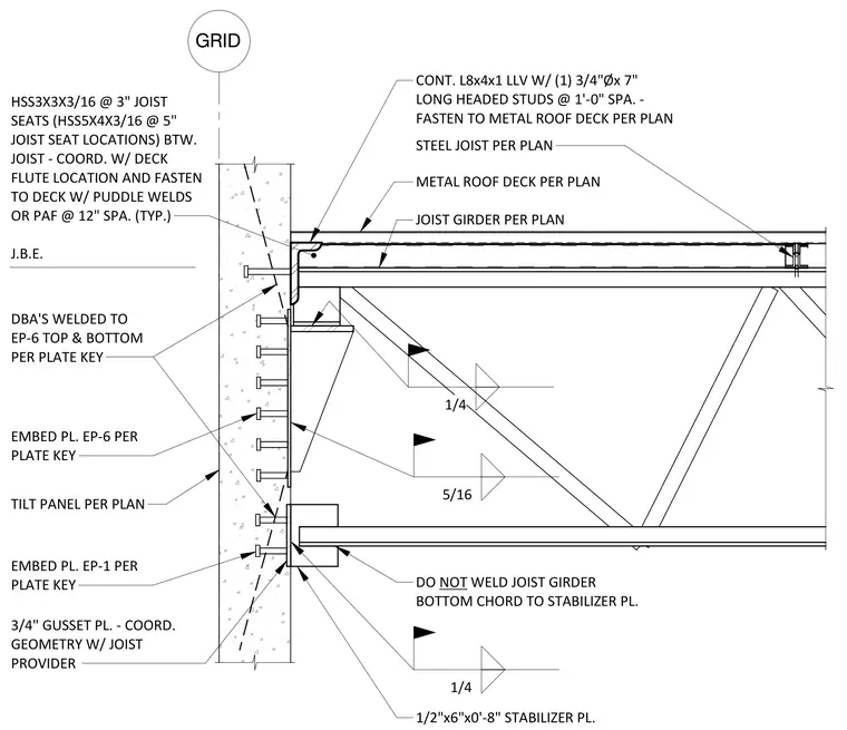
A continuous angle L8x4x1 with three-quarter-inch diameter by seven-inch long headed studs at one-foot spacing fastens to the metal roof deck at the top of the tilt-up wall panel. The steel joist girder bears onto embed plate EP-6, which is anchored to the tilt-up panel with welded deformed bar anchors top and bottom per the plate key. A three-quarter-inch thick gusset plate coordinates geometry with the joist provider, while an HSS3x3x3/16 member acts as a joist seat fastened to the deck with puddle welds or power-actuated fasteners at twelve-inch typical spacing. A half-inch by six-inch by zero-foot eight-inch stabilizer plate supports the joist girder bottom chord, left unwelded to the girder, and aligns with embed plate EP-1 per the plate key.
1 TILT PANEL PER PLAN EMBED PL. EP-6 PER PLATE KEY J.B.E. 1/2"x6"x0'-8" STABILIZER PL. DO NOT WELD JOIST GIRDER BOTTOM CHORD TO STABILIZER PL. EMBED PL. EP-1 PER PLATE KEY 1/4 JOIST GIRDER PER PLAN METAL ROOF DECK PER PLAN CONT. L8x4x1 LLV W/ (1) 3/4"Øx 7" LONG HEADED STUDS @ 1'-0" SPA. - FASTEN TO METAL ROOF DECK PER PLAN 3/4" GUSSET PL. - COORD. GEOMETRY W/ JOIST PROVIDER 5/16 1/4 HSS3X3X3/16 @ 3" JOIST SEATS (HSS5X4X3/16 @ 5" JOIST SEAT LOCATIONS) BTW. JOIST - COORD. W/ DECK FLUTE LOCATION AND FASTEN TO DECK W/ PUDDLE WELDS OR PAF @ 12" SPA. (TYP.) DBA'S WELDED TO EP-6 TOP & BOTTOM PER PLATE KEY GRID STEEL JOIST PER PLAN
Members view this detail in full resolution, download the CAD files (SVG, PDF), and can adapt it in the built-in CAD editor — export DXF, DWG, or PDF.
Start membership