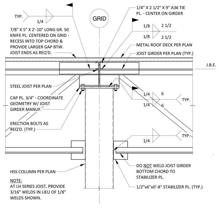
A hollow structural section column supports a three-quarter-inch cap plate connected with erection bolts. A seven-eighth-inch by five-inch by two-foot ten-inch Grade 50 knife plate is centered on the grid, recessed into the top chord, and provided with a larger gap between joist ends as required. A quarter-inch by two-and-a-half-inch by nine-inch A36 tie plate is centered on the girder. A half-inch by six-inch by eight-inch stabilizer plate is provided at the column, with the joist girder bottom chord left unwelded to the stabilizer plate. A metal roof deck bears over the top chords of the joist girder and steel joist per plan.
2 HSS COLUMN PER PLAN METAL ROOF DECK PER PLAN J.B.E. JOIST GIRDER PER PLAN (TYP.) STEEL JOIST PER PLAN 1/2"x6"x0'-8" STABILIZER PL. (TYP.) DO NOT WELD JOIST GIRDER BOTTOM CHORD TO STABILIZER PL. CAP PL. 3/4" - COORDINATE GEOMETRY W/ JOIST GIRDER MANUF. GRID 1/4 TYP. 1/8 2 1/2 1/8 2 1/2 1/4 6 1/4 6 TYP. 7/8" X 5" X 2'-10" LONG GR. 50 KNIFE PL. CENTERED ON GRID - RECESS INTO TOP CHORD & PROVIDE LARGER GAP BTW. JOIST ENDS AS REQ'D. 1/4 TYP. 1/4" X 2 1/2" X 9" A36 TIE PL. - CENTER ON GIRDER ERECTION BOLTS AS REQ'D. (TYP.) NOTE: AT LH SERIES JOIST, PROVIDE 3/16" WELDS IN LIEU OF 1/8" WELDS SHOWN.
Members view this detail in full resolution, download the CAD files (SVG, PDF), and can adapt it in the built-in CAD editor — export DXF, DWG, or PDF.
Start membership